Opel Frontera UBS. Service manual — part 2210
6A–30
ENGINE MECHANICAL (6VE1 3.5L)
014R100020
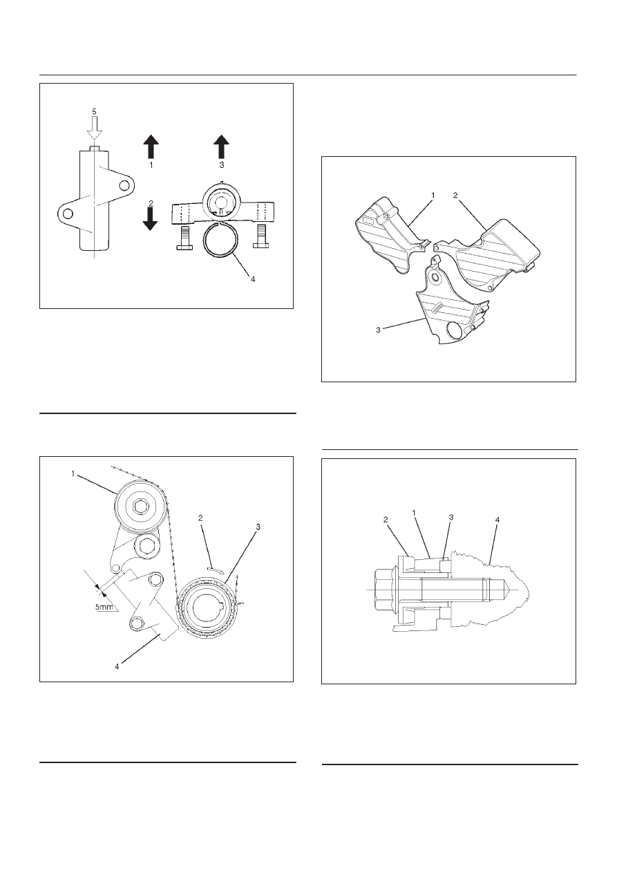
Legend
(1) Up Side
(2) Down Side
(3) Direction for Installation
(4) Locking Pin
(5) Apply a force of 980 N (100 kgf/220 lb) when
compressing the pusher rod.
After release the push rod from the locking pin,
the rod projection is approximate 5 mm (0.1969
in).
014R100032
Legend
(1) Tensioner Pulley
(2) Crankshaft Pulley Rotation Direction
(3) Crankshaft Pulley
(4) Pusher Assembly
3. Remove double clips or equivalent clips from
timing belt pulleys.
Turn the crankshaft pulley by six turns and check
for timing mark alignment.
3. Install timing belt cover.
Remove crankshaft pulley that was installed in step
1 item 5.
Tighten bolts to the specified torque.
Torque: 19 N·m (1.9 kg·m/14 lb ft)
020RW004
Legend
(1) Timing Belt Cover RH
(2) Timing Belt Cover LH
(3) Timing Belt Cover Lower
020RW003
Legend
(1) Timing Belt Cover
(2) Rubber Bushing
(3) Sealing Rubber
(4) Cylinder Body
4. Install crankshaft pulley using 5-8840-0133-0, hold
the crankshaft pulley and tighten center bolt to the
specified torque.
Torque : 167 N·m (17.0 kg·m/123 lb ft)
6A–31
ENGINE MECHANICAL (6VE1 3.5L)
5. Install fan pulley bracket and tighten fixing bolts to the
specified torque.
Torque : 22 N·m (2.2 kg·m/16 lb ft)
6. Install power steering pump assembly and tighten to
the specified torque.
Torque :
M8 bolt : 22 N·m (2.2 kg·m/16 lb ft)
M10 bolt : 46 N·m (4.7 kg·m/34 lb ft)
7. Install cooling fan assembly and tighten bolts/nuts to
the specified torque.
Torque : 22 N·m (2.2 kg·m/16 lb ft) for fan pulley
and fan bracket.
Torque : 10 N·m (1.0 kg·m/87 lb in) for fan and
clutch assembly.
8. Move drive belt tensioner to loose side using wrench,
then install drive belt to normal position.
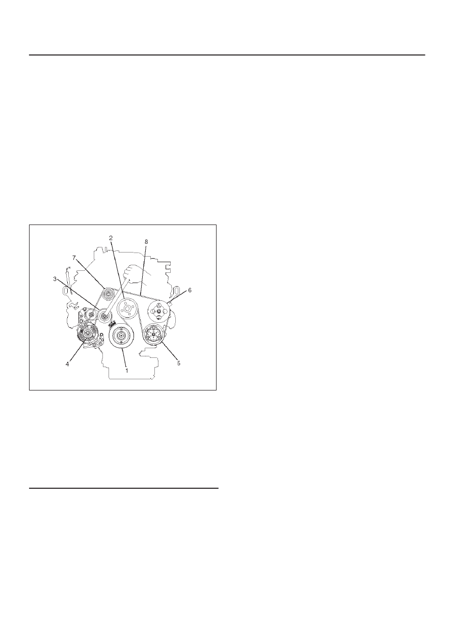
850RW001
Legend
(1) Crankshaft Pulley
(2) Cooling Fan Pulley
(3) Tensioner
(4) Generator
(5) Air Conditioner Compressor
(6) Power Steering Oil Pump
(7) Idle Pulley
(8) Drive Belt
9. Install radiator upper fan shroud.
10. Install air cleaner assembly.
6A–32
ENGINE MECHANICAL (6VE1 3.5L)
Camshaft
Removal
1. Disconnect battery ground cable.
2. Remove crankshaft pulley.
D
Refer to removal procedure for Crankshaft Pulley in
this manual.
3. Remove timing belt.
D
Refer to removal procedure for Timing Belt in this
manual.
4. Remove cylinder head cover LH.
D
Refer to removal procedure for Cylinder Head
Cover LH in this manual.
5. Remove cylinder head cover RH.
D
Refer to removal procedure for Cylinder Head
Cover RH in this manual.
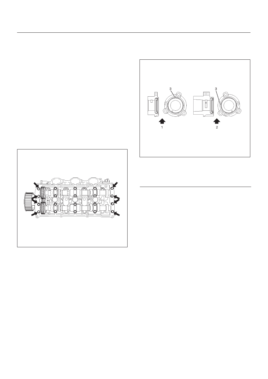
6. Remove twenty fixing bolts from inlet and exhaust
camshaft bearing cap on one side bank, then
camshaft bearing cap.
014RW027
7. Remove camshaft assembly.
8. Remove fixing bolt for camshaft drive gear pulley.
9. Remove three fixing bolts from camshaft drive gear
retainer, then camshaft drive gear assembly.
014RW026
Legend
(1) Right Bank
(2) Left Bank
(3) Timing Mark on Retainer
6A–33
ENGINE MECHANICAL (6VE1 3.5L)
Installation
1. Install camshaft drive gear assembly and tighten
three bolts to the specified torque.
Torque : 10 N·m (1.0 kg·m/87 lb in)
2. Tighten bolt for camshaft drive gear assembly pulley
to the specified torque.
Torque : 98 N·m (10.0 kg·m/72 lb ft)
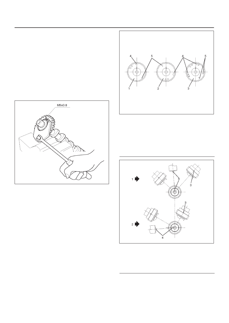
3. Tighten sub gear setting bolt.
1. Use 5-8840-2443-0 to turn sub gear to right
direction until it aligns with the M5 bolt hole
between camshaft driven gear and sub gear.
2. Tighten the M5 bolt to a suitable torque to prevent
the sub gear from moving.
014RW041
4. Install camshaft assembly and camshaft bearing
caps, tighten twenty bolts on one side bank to the
specified torque.
1. Apply engine oil to camshaft journal and bearing
surface of camshaft bearing caps.
2. Align timing mark on intake camshaft (one dot for
right bank, two dot for left bank) and exhaust
camshaft (one dots for right bank, two dots for left
bank) to timing mark on camshaft drive gear (one
dot).
014RW020
Legend
(1) Intake Camshaft Timing Gear for Right Bank
(2) Intake Camshaft Timing Gear for Left Bank
(3) Exhaust Camshaft Timing Gear
(4) Discrimination Mark
(LI: Left bank intake, RI: Right bank intake)
(LE: Left bank exhaust, RE: Right bank
exhaust)
014RW023
Legend
(1) Right Bank Camshaft Drive Gear
(2) Left Bank Camshaft Drive Gear
(3) Timing Mark on Drive Gear
(4) Dowel Pin
Нет комментариевНе стесняйтесь поделиться с нами вашим ценным мнением.
Текст