Opel Frontera UBS. Service manual — part 2102
6D3–7
STARTING AND CHARGING SYSTEM
Disassembly
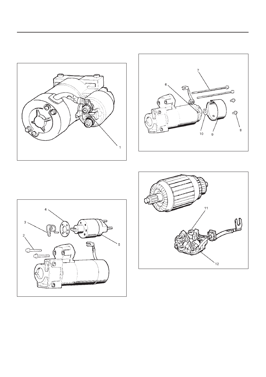
1. Loosen the nut(1) on terminal “M” of magnetic switch
and disconnect the connector cable.
2. Remove bolt (2 pcs) (2).
065RW003
3. Remove magnetic switch(5).
4. Remove dust cover(4).
5. Remove torsion spring bolts, then the magnetic
switch assembly.
6. Remove torsion spring(3) from magnetic switch
assembly(5).
065RW004
7. Remove screw (2 pcs) (8).
8. Remove through bolt (2 pcs) (7).
9. Remove screws and through bolts, then the rear
cover(9) then remove thrust washer(10).
10. Remove brush holder(6).
065RW005
11. Raise a brush spring to detach brushes (4 pcs) from
the commutator face and pull off the brush holder(12)
and brush(11).
065RW006
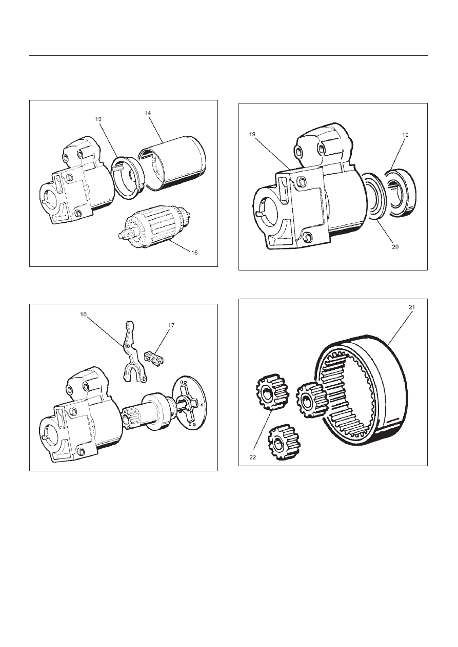
12. Remove yoke assembly(14).
13. Remove armature(15).
14. Pull off the yoke assembly, then remove armature,
washer and center bracket.(A) (13).
6D3–8
STARTING AND CHARGING SYSTEM
NOTE: In disassembling the yoke assembly, hold the
armature and pull off slowly the yoke assembly. Because
of strong magnetic force, avoid placing a metallic part
near armature.
065RW007
15. Remove dust cover(17).
16. Remove a dust cover and shift lever(16) from the gear
case.
065RW008
17. Remove ball bearing(19).
18. Remove bearing cover(20).
19. Remove a ball bearing and bearing cover from the
gear case(18).
065RW021
20. Internal gear(21).
21. Remove internal gear and planet gear(3) (22).
065RW009
6D3–9
STARTING AND CHARGING SYSTEM
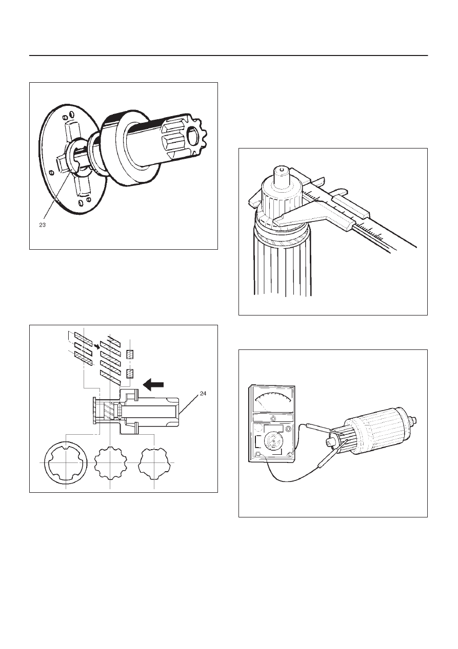
22. Remove an E–ring(23) from the pinion shaft using a
flat blade screwdriver.
065RW010
23. Holding the pinion shaft, push pinion toward the
center bracket. and turn the pinion clockwise or
counterclockwise by one tooth of spline, then pull off
the pinion.
24. Remove thrust washer(24).
25. Remove center bracket
26. Remove pinion shaft.
065RW011
Inspection and Repair
Repair or replace necessary parts if extreme wear or
damage is found during inspection.
Armature
Measure the outer diameter of commutator, and replace
with a new one if it is out of the limit.
Standard: 33.0 mm (1.30 in)
Limit: 32.0 mm (1.26 in)
065RS014
Check for continuity between commutator and segment.
Replace commutator if there is no continuity (i.e.,
disconnected).
065RS015
6D3–10 STARTING AND CHARGING SYSTEM
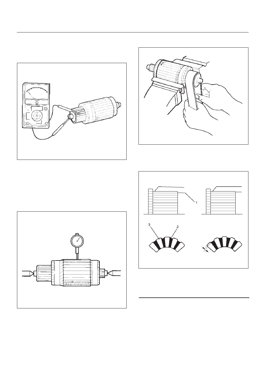
Check for continuity between commutator and shaft.
Also, check for continuity between commutator and
armature core,armature core and shaft. Replace
commutator if there is continuity (i.e., internally
grounded).
065RS016
Measure runout of armature core and commutator with a
dial gauge. Repair or replace, if it exceeds the limit.
Armature
Standard: 0.05 mm (0.002 in) Max.
Limit: 0.10 mm (0.004 in)
Commutator
Standard: 0.05 mm (0.002 in) Max.
Limit: 0.10 mm (0.004 in)
065RS017
Polish the commutator surface with sandpaper #500 to
#600 if it is rough.
065RW012
Measure the depth of insulator in commutator. Repair, if it
is below the limit.
Standard: 0.05 mm to 0.8 mm (0.02 in to 0.03 in)
Limit: 0.2 mm (0.008 in)
065RW013
Legend
(1) Steel Saw
(2) Insulator
(3) Commutator Segments
Нет комментариевНе стесняйтесь поделиться с нами вашим ценным мнением.
Текст