Opel Frontera UBS. Service manual — part 413
FUEL SYSTEM 6C – 9
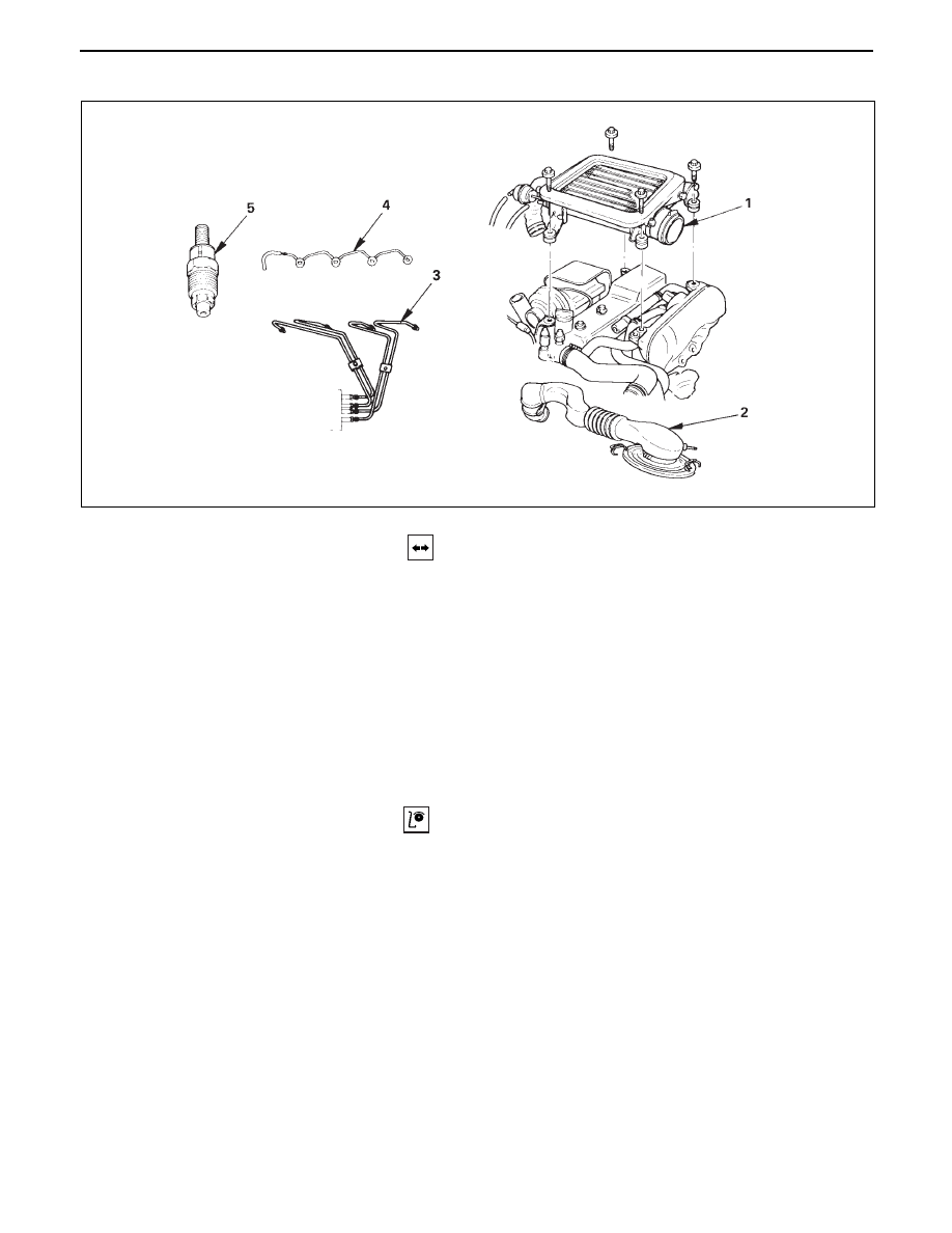
INJECTION NOZZLE
REMOVAL
Preparation:
•
Disconnect battery ground cable.
1.
Intercooler Assembly (4JG2-T Only)
•
(Refer to intercooler removal steps in section 6A2)
2.
Air Cleaner Cover & Air Duct
3.
Injection Pipe
•
Release injection pipe clip.
•
Loosen the flare nut on the injection pump side.
•
Loosen the flare nut on the injection nozzle side,
disconnect and put aside the pipe.
4.
Leak Off Pipe
5.
Injection Nozzle
INSPECTION
•
Set the nozzle in a nozzle tester.
Check there is no fuel leak in the nozzle seal when
a fuel pressure of 14710 kpa (150kg/cm
2
/2133 psi) is
applied.
If there is leak, replace.
6C – 10 FUEL SYSTEM
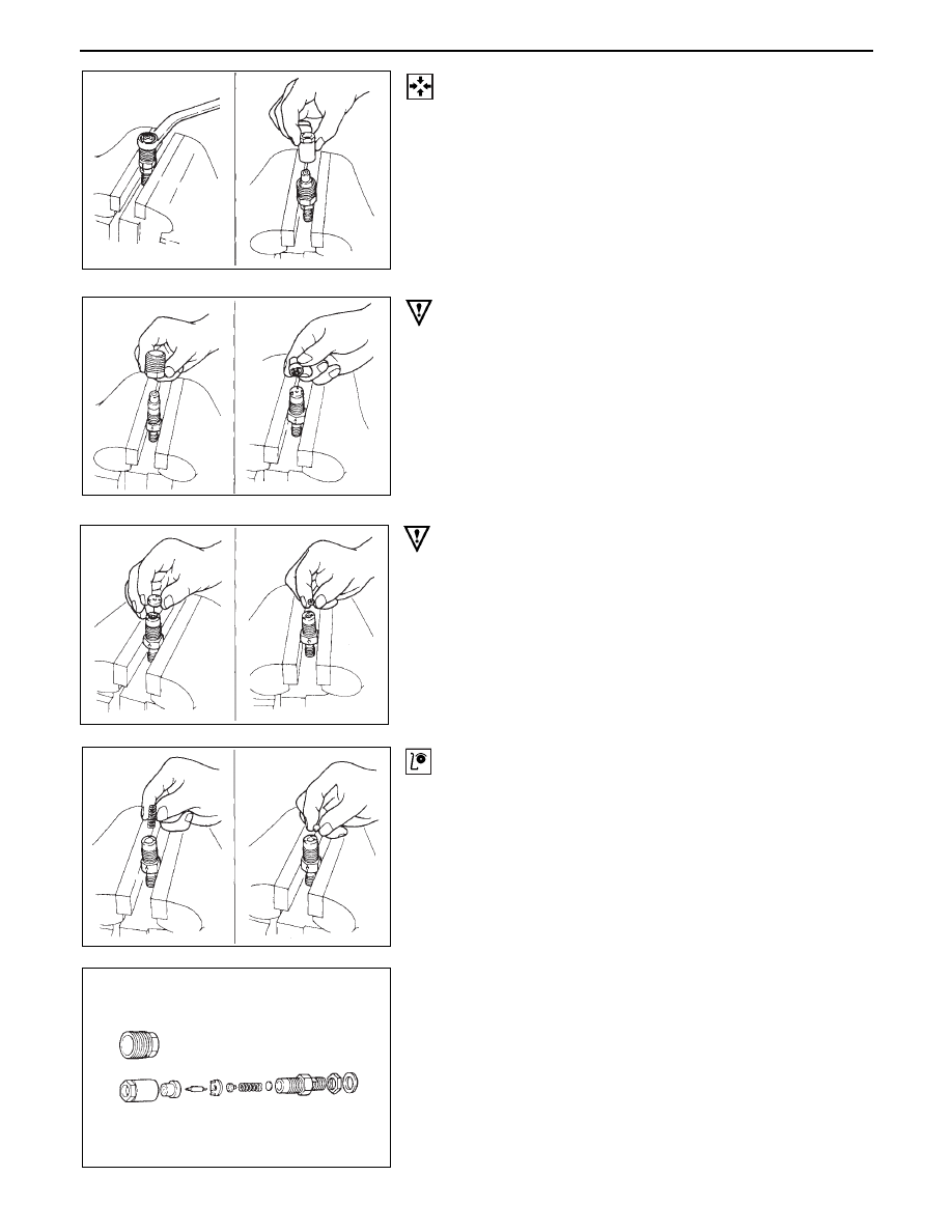
DISASSEMBLY
•
Grip nozzle holder with a vise, loosen retaining nut
and disassemble.
•
Loosen holder nut and remove the nozzle.
CAUTION
•
Be careful not to damage the needle valve.
•
Remove spacer, positioning pin, and push rod.
•
Remove spring and adjusting shim.
CAUTION
•
Wash all the parts removed and arrange them on a
cylinder basis, care should be taken not to miss any
parts.
•
Soak the nozzle assembly in a parts receptacle filled
with light oil.
•
Care should be taken not to miss shim, if used.
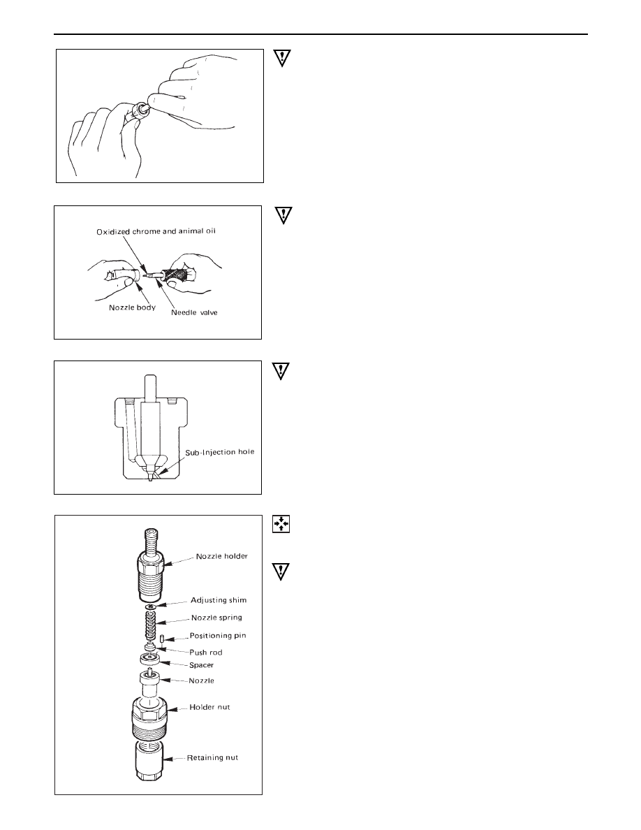
INSPECTION
Nozzle
•
Soak the nozzle removed in clean light oil, wash
nozzle body and needle valve separately, and check
and see that the needle valve slide smoothly in the
nozzle body.
FUEL SYSTEM 6C – 11
CAUTION
•
If the needle valve does not slide smoothly repair
or replace with a new nozzle assembly.
Nozzle lapping procedure
•
Apply thinly a compound (Chrome oxide kneaded
with an animal oil) to the seat of needle valve and
lap.
CAUTION
•
Excess compound may cause worn needle valve,
and be sure to wash out the compound after
lapping.
Nozzle body & needle
•
Check nozzle body end for seizure.
If significantly seized, replace as a nozzle assembly
basis. Also replace as a nozzle assembly basis, if
needle valve end is deformed or seized.
CAUTION
•
If either nozzle body or needle valve is faulty,
replace with a new nozzle assembly.
•
DFI’s sub hole is very small, care should be taken
not to allow foreign matter to get in.
REASSEMBLY
To reassemble, follow the removal steps in the reverse
order, noting the following point.
CAUTION
•
Be careful to fit spacer because positioning pins
are set off.
6C – 12 FUEL SYSTEM
•
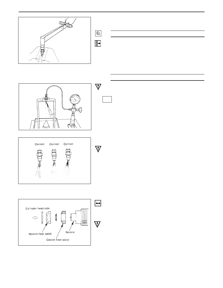
Install retaining nut and tighten nut to the specified
torque.
ADJUSTMENT OF INJECTION STARTING PRES-
SURE
•
Set nozzle holder asm on a nozzle tester.
•
Apply hydraulic pressure by operating tester
handle, and make sure fuel cam be injected under
the following pressure.
CAUTION
•
In case of DFI test results are O.K. if the sub-hole
inject fuel in spray.
14710 (150/2133)
Kpa (Kg/cm
2
/Psi)
CAUTION
•
If not injected under the specified pressure, adjust
with adjusting shim.
Ref.
Types are available in the 1.0 – 1.75 mm (0.039 –
0.069 in) thickness range (on a 0.01 mm (0.0004 in)
basis).
•
Unless extremely deformed spray in seen, there is
no problem.
INSTALLATION
DFI should be positioned correctly and then installed in
the cylinder head, because the sub-hole must be set in the
specified direction.
CAUTION
•
Nozzle and assembling should be as illustrated.
•
Use new heat shield and new corrugated washer.
5.
Injection Nozzle
•
Lightly tighten the holder nut to suck extent that the
nozzle holder can turn one word and one word.
•
Set positioning confirmation drilled hole (ø2) within
a nozzle turning angle of ± 5° against the cylinder
head-side positioning boss.
39 (4/35)
N·m (Kg·m/lb·ff)
Нет комментариевНе стесняйтесь поделиться с нами вашим ценным мнением.
Текст