Opel Frontera UBS. Service manual — part 1974
4B2–43
DRIVE LINE CONTROL SYSTEM (TOD)
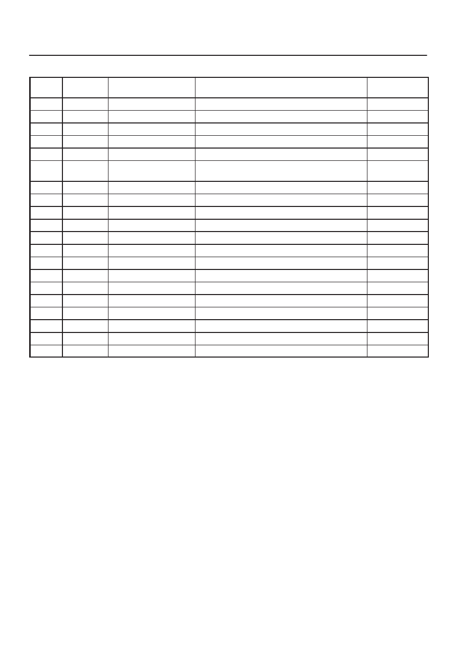
Diagnostic Trouble Codes
Code
Tech 2 code
(P code)
Item
Diagnosis
Check flow No.
12
—
Start code
Normal
—
13
P1735
Ref
Shorted GND
6
14
P1731
Front speed sensor
Input abnormality (open, sig or com)
2
15
P1736
Ref
Shorted V
B
6
16
P1737
Front speed sensor
Input abnormality
3
21
P1716
TPS
Shorted or disconnected wiring, abnormality in
input
7
23
—
ECU
CPU abnormality
1
24
P1733
Rear speed sensor
Input abnormality (open, sig or com)
5
25
—
CHECK lamp
Shorted
14
26
—
EMC (+)
Shorted GND
10
27
P1738
Rear speed sensor
Input abnormality
4
28
P1760
ADC (+) & AXLE SW
Output abnormality
11
31
P1721
EMC (+)
Shorted or disconnected coil/wiring
9
32
P1761
ADC (+)
Shorted or disconnected coil/wiring
12
33
P1762
ADC (+)
Shorted GND
13
34
—
D-G MAP
Input abnormality
8
35
—
CHECK lamp
Shorted or disconnected wiring
14
36
—
ECU
CPU abnormality
1
37
P1712
ECU
CPU abnormality
1
38
P1714
ECU
CPU abnormality
1
TPS : Throttle Position Sensor
EMC : Electromagnetic coil
ADC : Shift on the fly (Axle Dis Connect)
D-G MAP : Discrimination engine type
DRIVE LINE CONTROL SYSTEM (TOD)
4B2–44
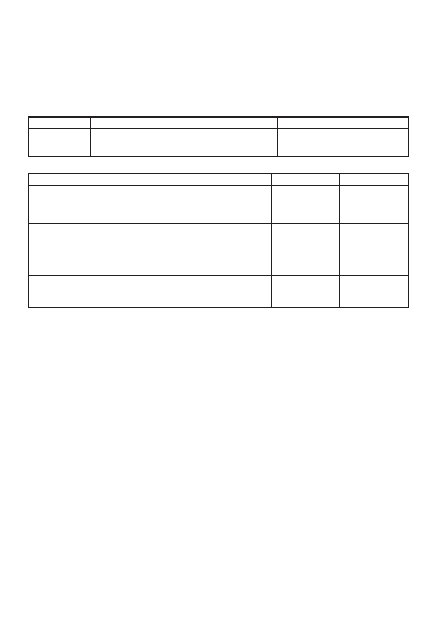
Diagnosis from Trouble Codes
D
Diagnose the TOD based on the fault that has been
saved to the control unit according to the system
self-diagnostic function.
Check flow
Trouble code
Phenomenon
Standard
1
23, 36,
37(P1712),
38(P1714)
The ECU has failed.
—
Step
Action
Yes
No
1
Turn on the starter switch.
Is the trouble reproduced?
Replace the ECU
and conduct the
test run.
Go to Step 3
Go to Step 2
2
1. Clear the trouble codes.
2. Conduct the test run.
Is the trouble reproduced during the test run?
Replace the ECU
and conduct the
test run.
Go to Step 3
The trouble is not
reproduced.
Refer to
“Troubles
intermittently
observed”.
3
1. Check that all the parts are mounted.
2. Clear the trouble codes.
Is this step complete?
Repeat the
“Diagnosis Flow”.
Return to Step 3
4B2–45
DRIVE LINE CONTROL SYSTEM (TOD)
Check flow
Trouble code
Phenomenon
Standard
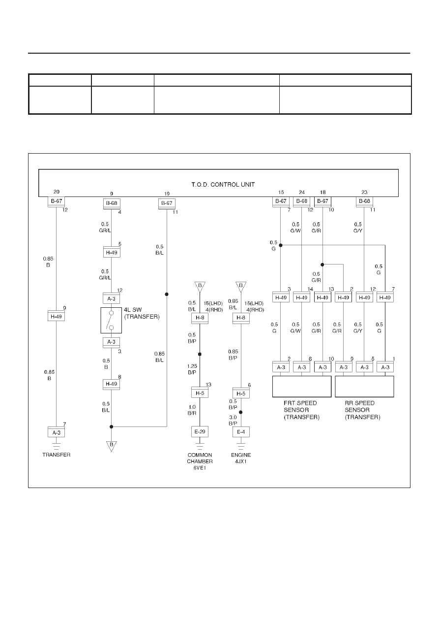
2
14
(P1733)
Front speed sensor signal open or
GND short, speed sensor com
open.
0.3V > sensor voltage
NOTE: The following procedure shows the case that the
front or rear sensor reference or common grounding line
is broken.
D04RY00059
DRIVE LINE CONTROL SYSTEM (TOD)
4B2–46
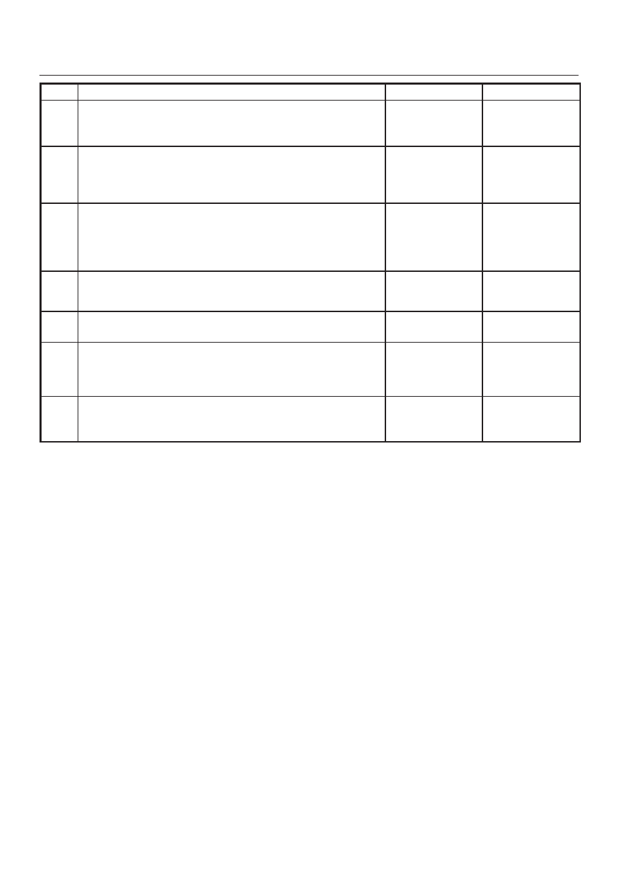
Step
Action
Yes
No
1
1. Start the engine.
2. Select TOD mode.
Is there the memory except DTC 14(P1731)?
Go to
Step 4
Go to
Step 2
2
1. Turn off the starter switch.
2. Disconnect the ECU connector (B–67) and (B–68).
Is there the continuity between the connector (B–68) terminal 12
and connector (B–67) terminal 11?
Repair the circuit.
Go to
Step 7
Go to
Step 3
3
1. Disconnect the transfer connector (A–3).
Is there the continuity between the connector (B–68) terminal 12
and the connector (A–3) terminal 6, the connector (B–67) terminal
7 and connector (A–3) terminal 2, and the connector (B–67)
terminal 10 and connector (A–3) terminal 10?
Replace the front
speed sensor.
Go to
Step 7
Repair the circuit.
Go to
Step 7
4
Is the memory DTC 24(P1733)?
Go to
Step 5
Refer to
other
trouble check
flow.
5
Is there the continuity between harnesses of terminal 24 and 23
(vehicle side terminal of the front and rear speed sensor)?
Go to
Step 6
Repair the circuit.
Go to
Step 7
6
Is there the continuity between harnesses of terminal 18 and 15
(vehicle side terminal of the speed sensor COM(–) and ref)?
Replace front and
rear speed
sensor.
Go to
Step 7
Repair the circuit.
Go to
Step 7
7
1. Check that all the parts are mounted.
2. Clear the trouble code.
Is the step complete?
Verify the repair.
Return to
Step 7
Нет комментариевНе стесняйтесь поделиться с нами вашим ценным мнением.
Текст