Opel Frontera UBS. Service manual — part 670
8D–110
WIRING SYSTEM
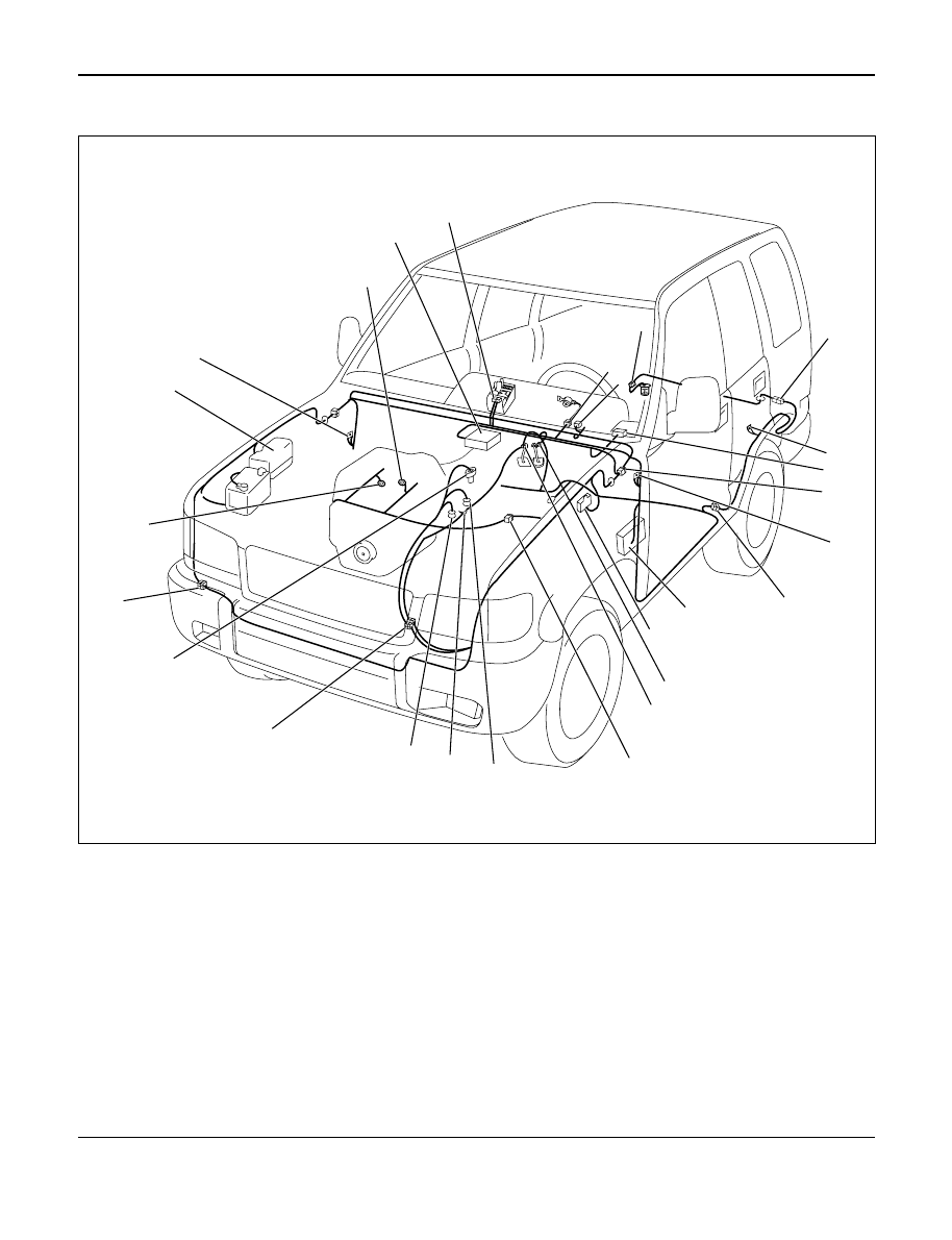
Parts Location (LHD 6V*1) – 2
2
1
26
24
25
23
22
21
20
19
18
17
16
15
14
13
12
11
10
7
9
6
8
5
3
4
D08RW913
Legend
(1) PCM
(2) B-30
(3) B-11
(4) F-4
(5) I-9
(6) H-33
(7) R-4
(8) C-63
(9) H-7, H-8, H-9
(10) B-18, B-19
(11) H-46
(12) Fuse Box
(13) C-16
(14) B-13 or B-14
(15) B-10
(16) H-5
(17) M-7
(18) M-25
(19) M-6
(20) H-10, H-11, H-53
(21) M-15
(22) H-41
(23) E-30
(24) Relay and Fuse Box
(25) B-2
(26) E-28, E-29
WIRING SYSTEM
8D–111
QOS-III (4JG2)
General Description
The circuit consists of the starter switch, QOS-III
control unit, glow relay, charge relay, fuel cut
solenoid, dropping resistor, thermo sensor, glow
indicator light (meter), glow plug and car speed
sensor. The engine coolant temperature at the time
of the engine start-up is sensed by the thermo
sensor to change the glow time so that the optimum
starting conditions can always be obtained.
The idling speed just after the engine start-up can
also be placed in the most suitable conditions in
accordance with the coolant temperature by the
operation of the delay timer.
The indicator timer is activated upon the starter
switch turned to the ON position, and the indicator
light comes on for as much time as suitable for the
engine coolant temperature at the time of the
engine start-up.
8D–112
WIRING SYSTEM
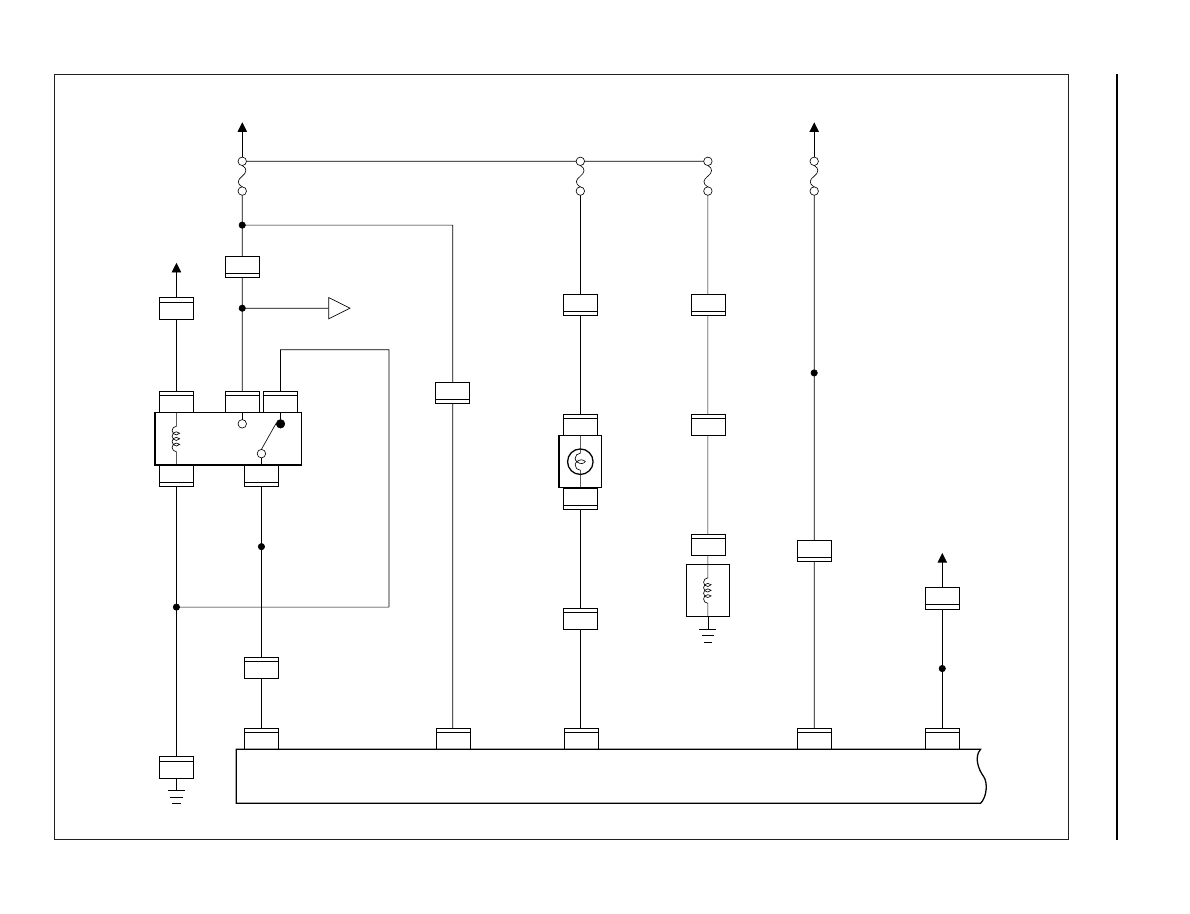
Circuit Diagram (RHD)-1
0.5
B
0.85
W/G
0.85
W/G
0.5
B
0.5
B/Y
0.85
B/Y
0.5
L/Y
0.5
L/Y
0.5
P/W
0.85
B/O
0.85
B/O
0.85
B/O
0.3
P/W
0.85
B/Y
0.85
B/Y
3.0
B/Y
C-8 15A
ENGINE
CHARGE
RELAY
GLOW
INDICATOR
LIGHT
(METER)
FUEL CUT
SOLENOID
0.85
W/L
QOS III CONTROL UNIT
C-66
6
C-66
1
C-66
13
C-66
11
C-66
9
C-39
1
X-17
2
I-9
15
H-41
12
H-9
14
X-17
3
X-17
5
H-3
3
1
X-17
26
I-9
4
X-17
FENDER-RH
STARTER SW
(IG1)
AC GENERATOR
(L)
C-10 10A
METER, GAUGE
C-9 15A
FUEL CUT
A
19
H-15
3.0
W/G
0.5
W/R
0.5
W/R
C-1 10A
STARTER
RELAY
STARTER SW
(ST)
4
H-7
0.5
LG/W
0.3
LG/W
VEHICLE SPEED
SENSOR(3)
15
H-5
12
H-7
6
H-26
H-5
7
7
E-37
1
H-7
D08RW982
WIRING SYSTEM
8D–113
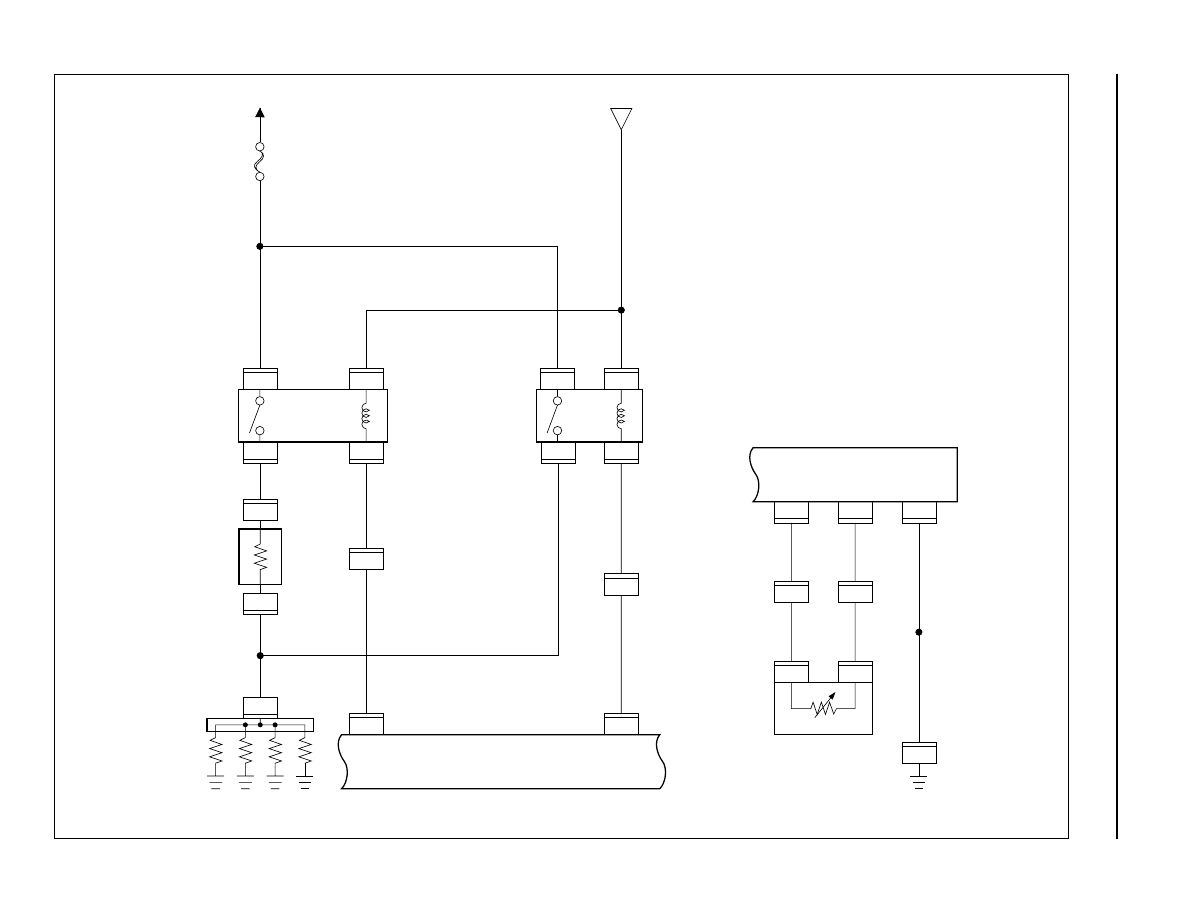
Circuit Diagram (RHD)-2
DROPPING
RESISTOR
GLOW
PLUG
GLOW
RELAY-2
QOS III CONTROL UNIT
GLOW
RELAY-1
C-66
12
H-42
16
1
1
C-60
C-59
3.0
R/W
3.0
B/Y
3.0
B/R
0.5
B/G
0.5
B/G
0.85
B/Y
FL-5 50A
GLOW
C-53
1
C-59
2
1
C-54
BATT.(+)
C-55
1
2
C-55
A
C-66
5
H-41
7
3.0
B/R
0.5
B/L
0.5
B/L
0.85
B/Y
0.85
B/Y
3.0
R/W
C-51
1
C-51
C-52
1
2
2
C-52
1
2
E-41
E-41
QOS THERMO SENSOR
(ENGINE)
QOS III CONTROL UNIT
C-16
0.5
B
0.5
Y
0.5
Y
0.5
B/Y
0.5
B
7
C-66
10
FENDER
-LH
C-66
8
C-66
4
H-4
8
H-4
12
D08RW980
Нет комментариевНе стесняйтесь поделиться с нами вашим ценным мнением.
Текст