Opel Frontera UBS. Service manual — part 2381
6H–2
ENGINE SPEED CONTROL SYSTEM (6VE1 3.5L)
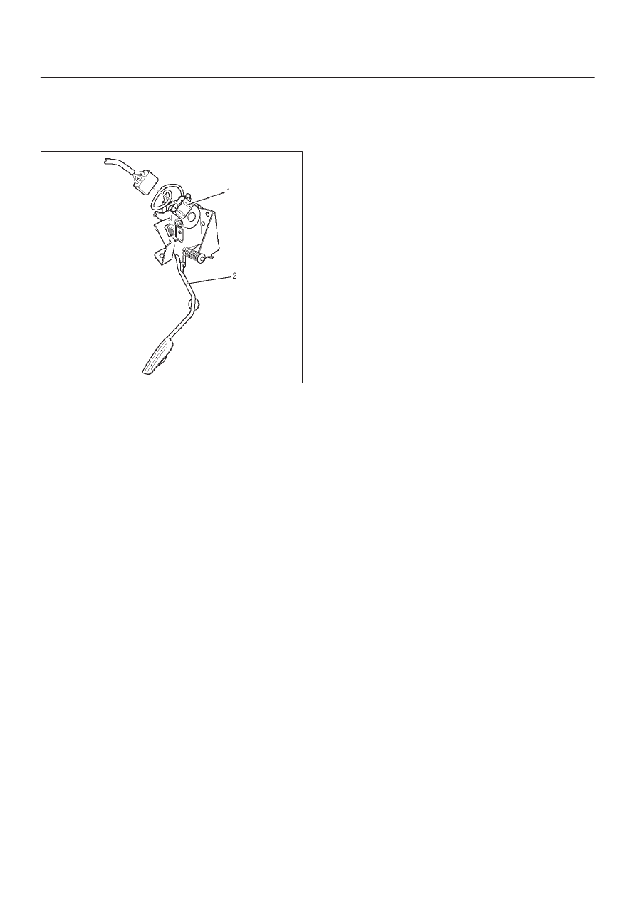
Accelerator Pedal
Accelerator Pedal and Associated
Parts
101RY00006
Legend
(1) Accelerator Position Sensor
(2) Accelerator Pedal Assembly
Removal
1. Disconnect battery ground cable.
2. Disconnect Accelerator position (AP) sensor (1)
connector from Accelerator pedal assembly.
3. Remove Accelerator pedal assembly (2).
Installation
1. Install Accelerator pedal assembly (2).
2. Connect AP sensor (1) harness connector.
3. Connect battery ground cable.
INDUCTION
6J–1
ENGINE
INDUCTION
CONTENTS
Service Precaution
6J–1
. . . . . . . . . . . . . . . . . . . . . .
Air Cleaner Element
6J–2
. . . . . . . . . . . . . . . . . . . . .
Removal
6J–2
. . . . . . . . . . . . . . . . . . . . . . . . . . . . .
Inspection
6J–2
. . . . . . . . . . . . . . . . . . . . . . . . . . . .
Installation
6J–2
. . . . . . . . . . . . . . . . . . . . . . . . . . . .
Service Precaution
WARNING: THIS VEHICLE HAS A SUPPLEMENTAL
RESTRAINT SYSTEM (SRS). REFER TO THE SRS
COMPONENT AND WIRING LOCATION VIEW IN
ORDER TO DETERMINE WHETHER YOU ARE
PERFORMING SERVICE ON OR NEAR THE SRS
COMPONENTS OR THE SRS WIRING. WHEN YOU
ARE PERFORMING SERVICE ON OR NEAR THE SRS
COMPONENTS OR THE SRS WIRING, REFER TO
THE SRS SERVICE INFORMATION. FAILURE TO
FOLLOW WARNINGS COULD RESULT IN POSSIBLE
AIR BAG DEPLOYMENT, PERSONAL INJURY, OR
OTHERWISE UNNEEDED SRS SYSTEM REPAIRS.
CAUTION: Always use the correct fastener in the
proper location. When you replace a fastener, use
ONLY the exact part number for that application.
ISUZU will call out those fasteners that require a
replacement after removal. ISUZU will also call out
the fasteners that require thread lockers or thread
sealant. UNLESS OTHERWISE SPECIFIED, do not
use supplemental coatings (Paints, greases, or other
corrosion inhibitors) on threaded fasteners or
fastener joint interfaces. Generally, such coatings
adversely affect the fastener torque and the joint
clamping force, and may damage the fastener. When
you install fasteners, use the correct tightening
sequence and specifications. Following these
instructions can help you avoid damage to parts and
systems.
6J–2
INDUCTION
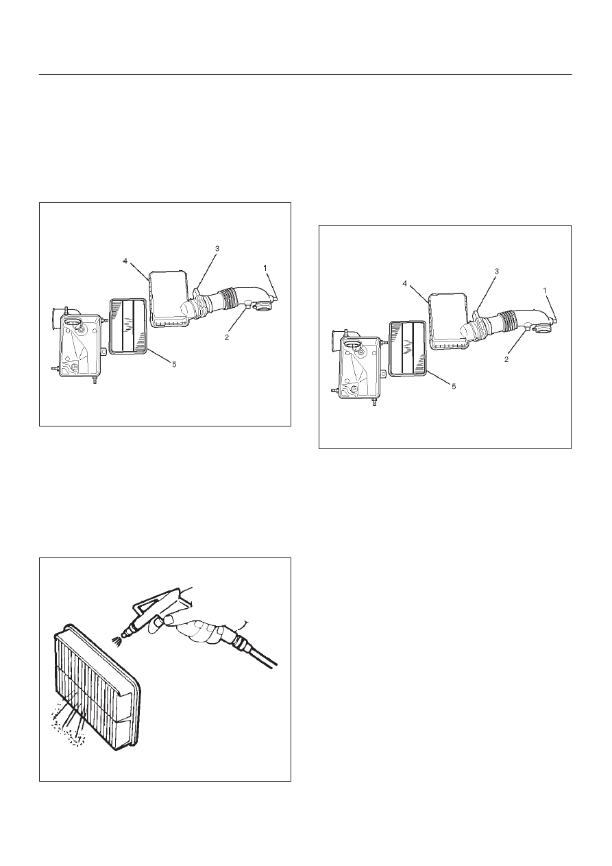
Air Cleaner Element
Removal
1. Remove positive ventilation hose from connector(1).
2. Remove intake air temperature sensor(2).
3. Remove air flow sensor(3).
4. Remove air cleaner duct cover(4).
5. Remove air cleaner element(5).
130RW003
Inspection
Check the air cleaner element for damage or dust
clogging. Replace if it is damaged, or clean if it is clogged.
Cleaning Method
Tap the air cleaner element gently so as not to damage
the paper element, or clean the element by blowing with
compressed air of about 490 kPa (71 psi) from the clean
side if it is extremely dirty.
130RW002
Installation
1. Install air cleaner element(5).
2. Attach the air cleaner duct cover (4) to the body
completely, then clamp it with the clip.
3. Install mass air flow sensor(3).
4. Install air temperature sensor(2).
5. Connect positive crankcase ventilation hose to
connector(1).
130RW003

ENGINE MECHANICAL 6A – 1
ENGINE
ENGINE MECHANICAL
CONTENTS
General Description . . . . . . . . . . . . . . . . . . . .
6A–2
Service Information . . . . . . . . . . . . . . . . . . . .
6A–3
Service Standard . . . . . . . . . . . . . . . . . . . . . .
6A–6
Servicing . . . . . . . . . . . . . . . . . . . . . . . . . . . .
6A–9
Tightening Torque . . . . . . . . . . . . . . . . . . . . . 6A–14
Special Tools . . . . . . . . . . . . . . . . . . . . . . . . . 6A–25
Engine Assembly . . . . . . . . . . . . . . . . . . . . . . 6A–28
Engine Mount (RH) . . . . . . . . . . . . . . . . . . . . 6A–30
Engine Mount (LH). . . . . . . . . . . . . . . . . . . . . 6A–31
Intercooler . . . . . . . . . . . . . . . . . . . . . . . . . . . 6A–32
Cylinder Head Cover . . . . . . . . . . . . . . . . . . . 6A–33
Intake Manifold . . . . . . . . . . . . . . . . . . . . . . . 6A–35
Exhaust Manifold . . . . . . . . . . . . . . . . . . . . . . 6A–36
Turbocharger . . . . . . . . . . . . . . . . . . . . . . . . . 6A–38
Cylinder Head . . . . . . . . . . . . . . . . . . . . . . . . 6A–41
Cylinder Head Gasket . . . . . . . . . . . . . . . . . . 6A–43
Camshaft . . . . . . . . . . . . . . . . . . . . . . . . . . . . 6A–47
Timing Gear. . . . . . . . . . . . . . . . . . . . . . . . . . 6A–52
Valve Stem Seal, Valve Spring and Adjuster . . 6A–60
Valve Clearance Adjustment. . . . . . . . . . . . . . 6A–67
Oil Rail and Injector . . . . . . . . . . . . . . . . . . . . 6A–69
Crank Case . . . . . . . . . . . . . . . . . . . . . . . . . . 6A–72
Crankshaft . . . . . . . . . . . . . . . . . . . . . . . . . . . 6A–74
Piston and Connecting Rod . . . . . . . . . . . . . . 6A–84
Cylinder Block . . . . . . . . . . . . . . . . . . . . . . . . 6A–92
Oil Pump Assembly . . . . . . . . . . . . . . . . . . . . 6A–98
Oil Filter Cartridge . . . . . . . . . . . . . . . . . . . . . 6A–99
Oil Cooler . . . . . . . . . . . . . . . . . . . . . . . . . . . 6A–99
Нет комментариевНе стесняйтесь поделиться с нами вашим ценным мнением.
Текст