Opel Frontera UBS. Service manual — part 1339
6B – 10 ENGINE COOLING
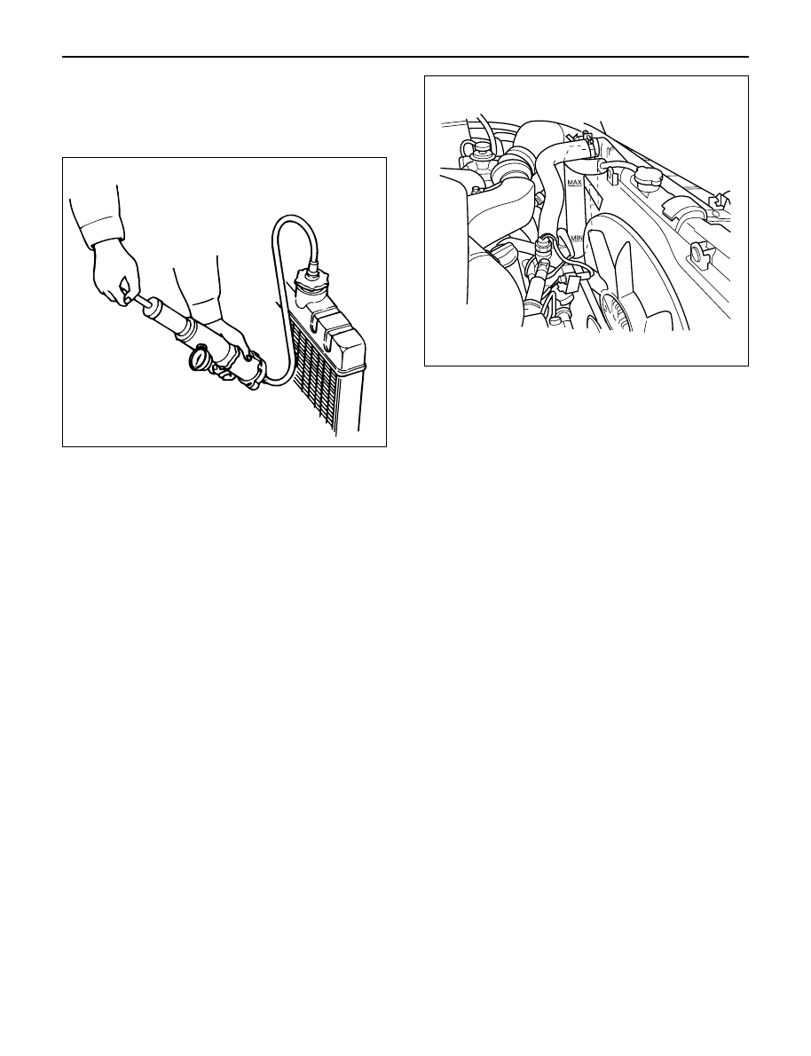
Checking for Coolant Leakage
1) Check the cooling system for leakage with the
radiator cap tester by applying 196.0 kPa (28.4 psi)
air pressure from filler neck to inside the radiator.
INSTALLATION
1. Radiator Assembly
1) Install rubber cushions on both sides of radiator
bottom.
2) Install radiator assembly with hose, taking care
not to damage the radiator core by a fan blade.
2. Bracket
1) Support the radiator upper tank with the bracket
and fix the radiator.
3. Reserve Tank Hose
4. Fan Guide, Lower
5. Radiator Hose
1) Connect inlet hose and outlet hose to the
engine.
2) Connect battery ground cable.
3) Pour coolant up to filler neck of radiator, and up
to MAX mark of reserve tank.
4) Start engine to warm up, and check for coolant
level. Replenish coolant if it does not reach the
radiator filler neck, and tighten the cap
completely.
110RS005
012RW080
ENGINE COOLING 6B – 11
DRIVE BELT ADJUSTMENT
INSPECTION
Check drive belts for wear or damage, and replace with
new ones as necessary. Check belts for tension, and
adjust as necessary.
1) Check drive belt tension.
2) Push the middle of belt with a force of 98 N
(10 kg/22 lb) and check each belt for deflection.
Standard deflection:
For A.C. generator & fan pulley drive belt
Initial tension : 8 – 12 mm (0.31 – 0.47 in)
Tension at readjustment : Same as above.
For A/C compressor drive belt
Initial tension : 7 – 10 mm (0.28 – 0.38 in)
Tension at readjustment : 5 – 8 mm (0.20 – 0.31 in)
TENSION ADJUSTMENT
1) Loosen AC generator mounting bolt to move AC
generator, adjust belt tension and tighten to the
specified torque.
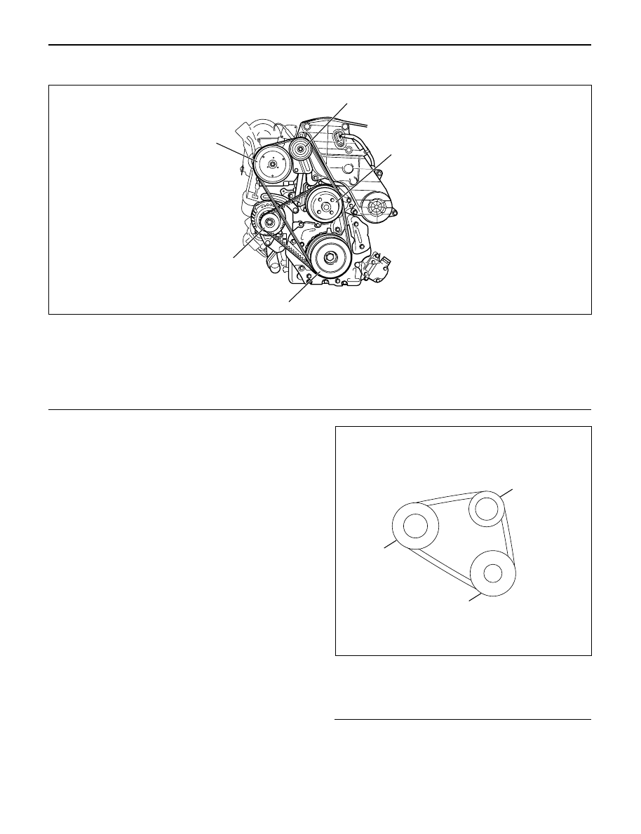
Legend
(1) Crankshaft Pulley
(2) A.C. Generator Pulley
(3) Cooling Fan Pulley
5
3
1
2
4
Legend
(1)
Crankshaft Pulley
(2)
A.C. Generator
(3)
Cooling Fan Pulley
(4)
A/C Compressor
(5)
Belt Tensioner Pulley
012RW085
3
2
1
012RW084
6B – 12 ENGINE COOLING
Torque:
For A.C. Generator fixing bolt
40 N·m (4.1 kg·m/29.7 lb ft)
For Adjusting plate fixing bolt
24 N·m (2.4 kg·m/17.4 lb ft)
For Adjusting plate lock bolt
19 N·m (1.9 kg·m/13.7 lb ft)
2) Adjust the A/C compressor drive belt by tightening
the belt tensioner bolt.
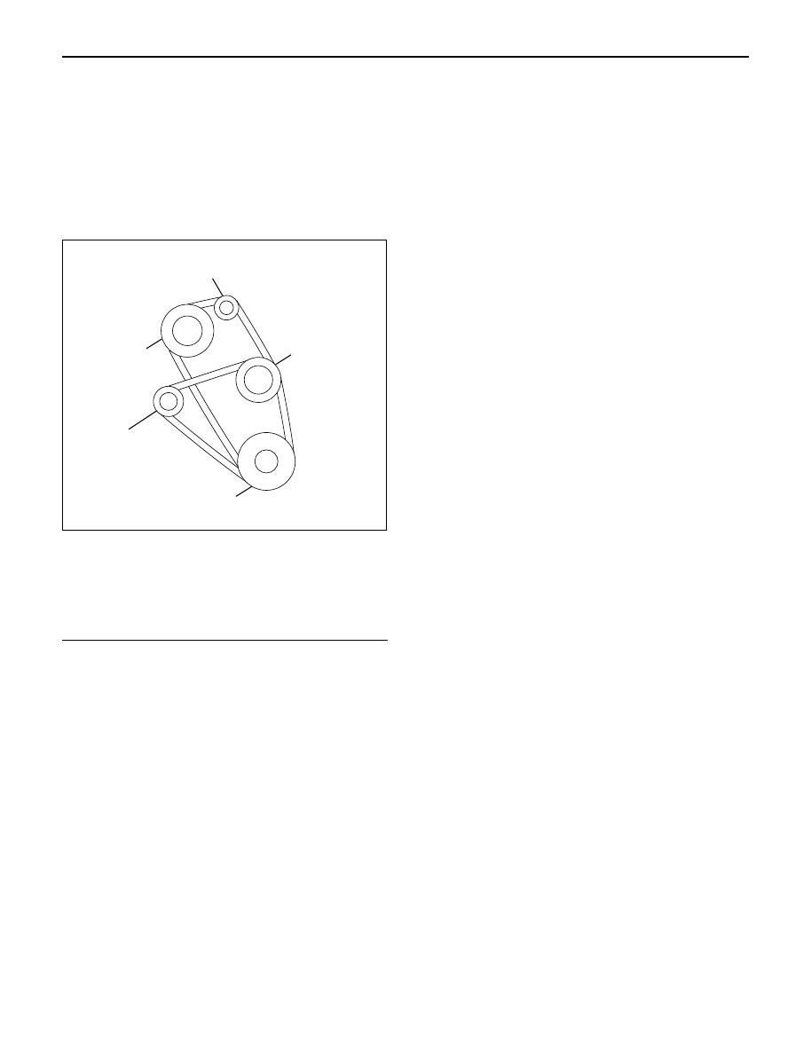
Legend
(1) Crankshaft Pulley
(2) A.C. Generator Pulley
(3) Cooling Fan Pulley
(4) A/C Compressor Pulley
(5) Belt Tensioner Pulley
5
3
2
4
1
012RW110
ENGINE FUEL 6C – 1
ENGINE FUEL
CONTENTS
GENERAL DESCRIPTION
General Description . . . . . . . . . . . . . . . . . .
6C–1
On-Vehicle Service . . . . . . . . . . . . . . . . . .
6C–8
Fuel Filter Assembly . . . . . . . . . . . . . . . .
6C–8
Fuel Filter Cartridge . . . . . . . . . . . . . . . .
6C–8
Injector . . . . . . . . . . . . . . . . . . . . . . . . . .
6C–10
High Pressure Oil Pump . . . . . . . . . . . . .
6C–14
Fuel Tank . . . . . . . . . . . . . . . . . . . . . . . .
6C–20
Fuel Gauge Unit . . . . . . . . . . . . . . . . . . .
6C–21
Fuel Filler Cap . . . . . . . . . . . . . . . . . . . .
6C–21
To realize the compatibility between low exhaust
emission and high engine output, an HEUI
(Hydraulically actuated Electronically controlled Unit
Injector) system, has been introduced. This system is
comprised of a hydraulic system, fuel system, and
electronic control system, using a high-pressure oil
pump in place of the conventional fuel injection pump.
The oil pressurized by means of this pump and by
signals from the ECM (Electronic Control Module)
actuates the fuel injector provided for each cylinder.
Inside of the fuel injector, fuel pressure is increased due
to the high-pressure oil. The ECM detects the driving
state of the vehicle, forms, signals sent by engine and
other part sensors, which determines the optimum fuel
injection amount and timing, thus controlling the fuel
injectors. Thus high engine output, good fuel economy,
and low exhaust emission are realized.
When working on the fuel system, there are several
things to keep in mind:
1) Any time the fuel system is being worked on,
disconnect the negative battery cable except for
those tests where battery voltage is required.
2) Always keep a dry chemical (Class B) fire
extinguisher near the work area.
3) Replace all pipes with the same pipe and fittings
that were removed.
Clean and inspect “O” rings. Replace where
required.
4) Always relieve the line pressure before servicing
any fuel system components.
5) Do not attempt repairs on the fuel system until you
have read the instructions and checked the pictures
relating to that repair.
6) After maintenance work, push priming pump and
send enough fuel to the fuel system before starting
the engine.
NOTE: In comparison with the conventional engine,
the capacity of fuel passage in the 4JX1 engine is
larger. It takes the priming pump more time to fill the
engine with fuel.
Нет комментариевНе стесняйтесь поделиться с нами вашим ценным мнением.
Текст