Opel Frontera UBS. Service manual — part 443
6A – 62 ENGINE MECHANICAL
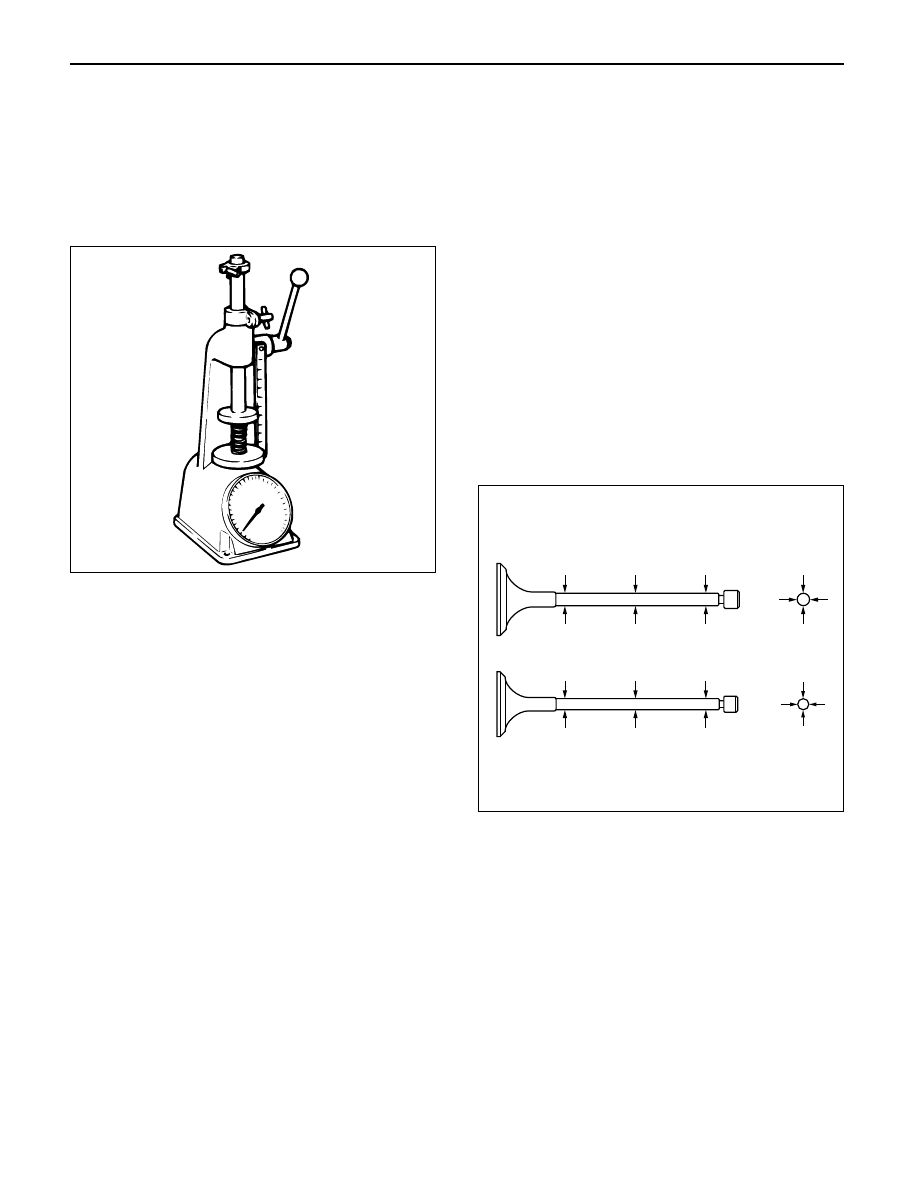
3. Spring tension
1) Use a spring tester to compress the springs to
the installed height. Measure the compressed
spring tension.
2) Replace the springs if the measured tension is
below the specified limit.
Standard: 236.0 N (24 kg/53 lb)
Limit: 205.0 N (21 kg/46 lb)
Valve Guide
CAUTION: Taking care not to damage the valve seat
contact surface, when removing carbon adhering to
the valve head.
Carefully inspect the valve stem for scratching or
abnormal wear. If these conditions are present, the
valve and the valve guide must be replaced as a set.
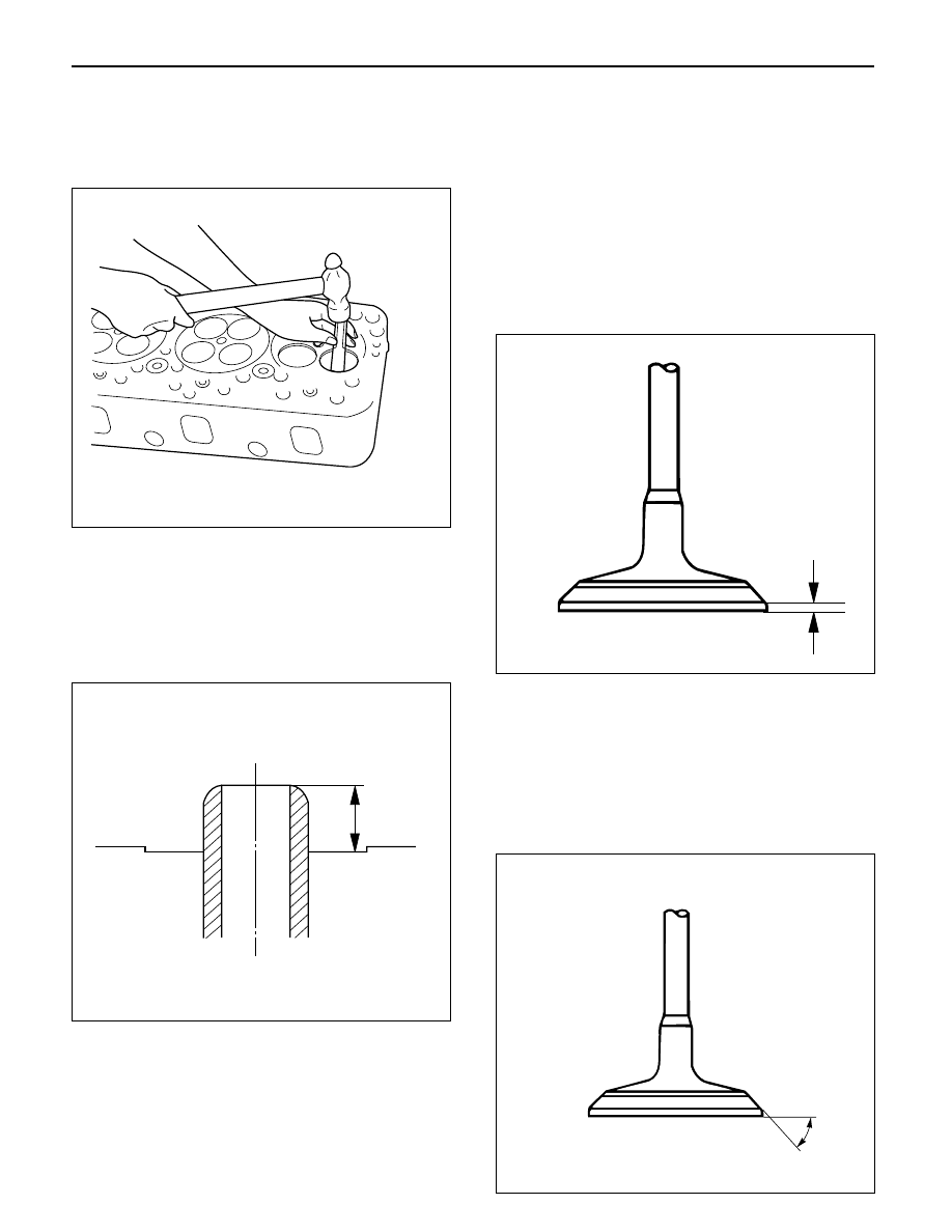
1. Valve Guide Clearance
1) Measure the valve stem diameter with a
micrometer.
If the valve stem diameter is less than the
specified limit, the valve and the valve guide
must be replaced as a set.
Diameter of Valve stem:Inlet
Standard: 6.959 – 6.977 mm (0.2740 – 0.2747 in)
Limit: 6.92 mm (0.2724 in)
Diameter of Valve stem:Exhaust
Standard: 6.952 – 6.97 mm (0.2737 – 0.2744 in)
Limit: 6.90 mm (0.2717 in)
2) Measure the inside diameter of the valve guide
with a micrometer.
3) Subtract the measured outer diameter of the
valve stem from the measured inner diameter of
the valve guide.
If the valve exceeds the specified limit, the valve
and the valve guide must be replaced as a set.
Inlet clearance
Standard: 0.023 – 0.053 mm (0.0009 – 0.0021 in)
Limit: 0.19 mm (0.0075 in)
Exhaust clearance
Standard: 0.03 – 0.063 mm (0.0012 – 0.0025 in)
Limit: 0.20 mm (0.0079 in)
014RS006
014RS007
ENGINE MECHANICAL 6A – 63
Valve Guide Replacement
1. Using the special tool, drive out the valve guide
from the combustion chamber side.
Valve guide replacer: 9-8523-1212-0
2. Apply engine oil to the outside of the valve guide.
Using the special tool, drive in a new valve guide
from cylinder head upper face side, and check the
valve guide height.
Valve guide replacer: 9-8523-1212-0
Height: 8.0 mm (0.315 in)
NOTE: If the valve guide has been removed, both the
valve and the valve guide must be replaced as a set.
Valve Thickness
1. Measure the valve thickness.
2. If the measured value is less than the specified
limit, the valve and the valve guide must be
replaced as a set.
Inlet
Standard: 1.2 mm (0.0472 in)
Limit: 1.1 mm (0.0433 in)
Exhaust
Standard: 1.2 mm (0.0472 in)
Limit: 1.1 mm (0.0433 in)
Contact surface angle on valve seat on
valve
1. Measure contact surface angle on valve seat.
2. If the measured value exceeds the limit, replace
valve, valve guide and valve seat as a set.
Standard: 68°
011RW001
012RW052
012RW060
014RW018
6A – 64 ENGINE MECHANICAL
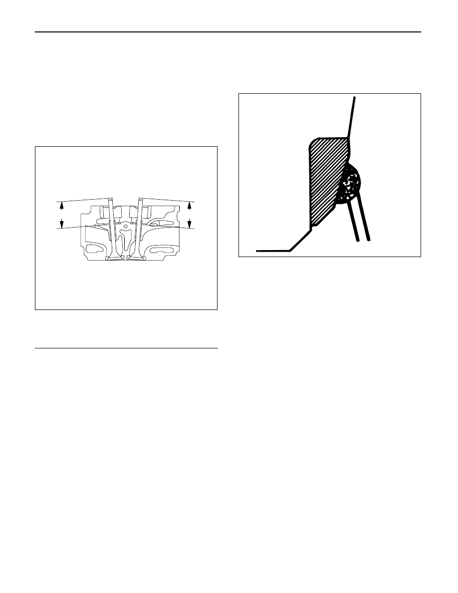
Valve Depression
1. Measure the valve stem height from the upper
surface of the cylinder head as shown in the
illustration.
Standard:
Intake side
35.59 mm (1.4012 in)
Exhaust side 35.49 mm (1.3972 in)
Limit:
Intake side
35.74 mm (1.4071 in)
Exhaust side 35.64 mm (1.4031 in)
Legend
(1) Intake Side
(2) Exhaust Side
Valve Contact Width
1. Check the valve contact faces for roughness and
unevenness. Make the valve contact surfaces
smooth.
2. Measure the valve contact width.
If the measured value exceeds the specified limit,
the valve seat insert must be replaced.
Inlet
Standard: 2.1 mm (0.0827 in)
Limit: 2.6 mm (0.1024 in)
Exhaust
Standard: 2.0 mm (0.0787 in)
Limit: 2.5 mm (0.0984 in)
Valve Seat Insert Replacement
Valve Seat Insert Removal
1. Arc weld the entire inside circumference of the
valve seat insert.
2. Allow the valve seat insert to cool for a few minutes.
This will invite contraction and make removal of the
valve seat insert easier.
3. Use a screwdriver to pry the valve seat insert free.
Take care not to damage the cylinder head.
4. Carefully remove carbon and other foreign material
from the cylinder head insert bore.
1
2
011RW044
014RS015
ENGINE MECHANICAL 6A – 65
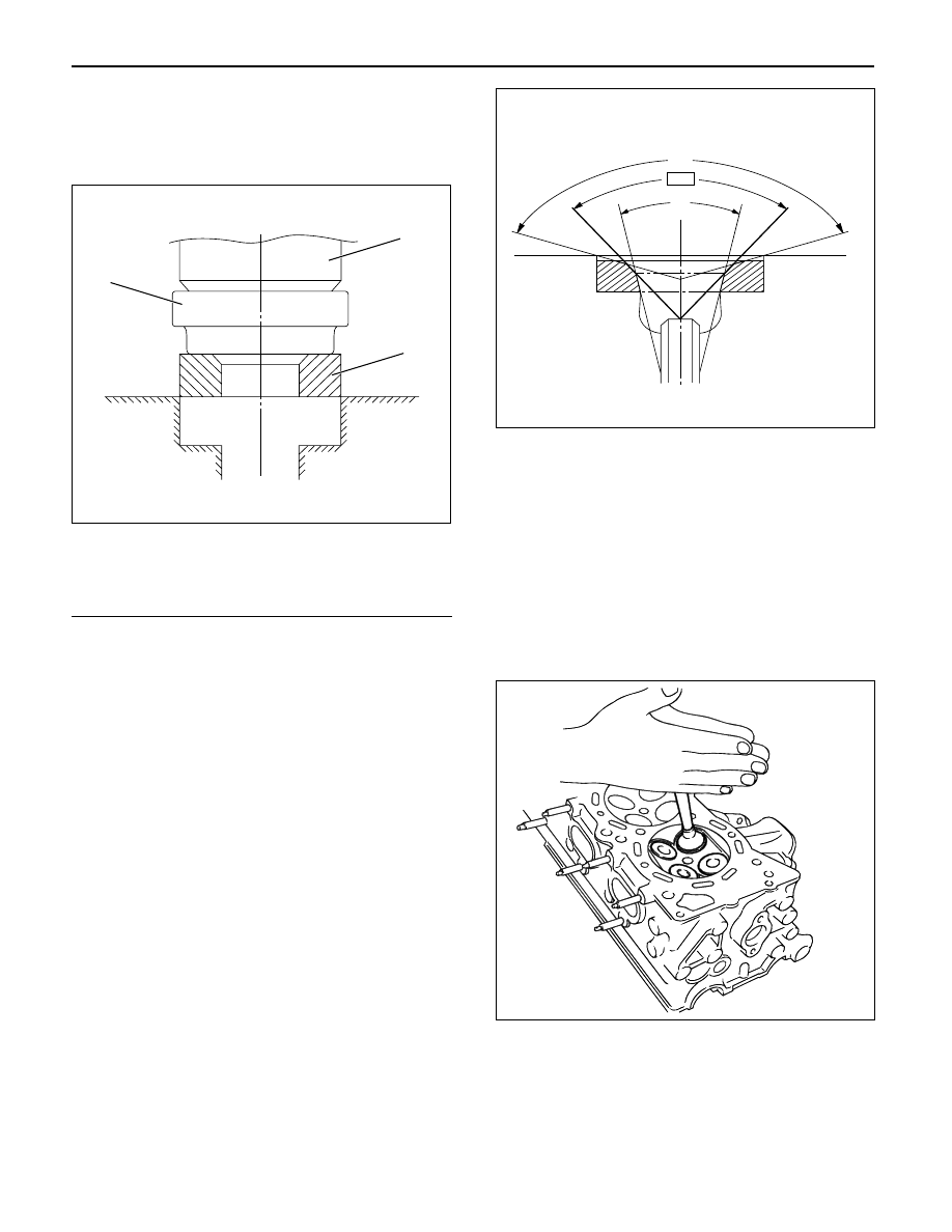
Valve Seat Insert Installation
1. Carefully place the attachment (1) (having a smaller
outside diameter than the valve seat insert) on the
valve seat insert (2).
Legend
(1) Attachment
(2) Valve Seat Insert
(3) Bench Press
NOTE: The smooth side of the attachment must contact
the valve seat insert.
2. Use a bench press (3) to gradually apply pressure
to the attachment and press the valve seat insert
into place.
Note: Do not apply an excessive amount of pressure
with the bench press. Damage to the valve seat insert
will result.
Valve Seat Insert Correction
1. Remove the carbon from the valve seat insert
surface.
2. Use a valve cutter (15°, 45° and 75° blades) to
minimize scratches and other rough areas. This will
bring the contact width back to the standard value.
Remove only the scratches and rough areas. Do
not cut away too much. Take care not to cut away
unblemished areas of the valve seat surface.
Valve Seat Angle: 45°
NOTE: Use an adjustable valve cutter pilot.
Do not allow the valve cutter pilot to wobble inside the
valve guide.
3. Apply abrasive compound to the valve seat insert
surface.
4. Insert the valve into the valve guide.
5. Turn the valve while tapping it to fit the valve seat
insert.
6. Check that the valve contract width is correct.
7. Check that the valve seat insert surface is in
contact with the entire circumference of the valve.
3
2
1
012RW055
150
°
90
°
30
°
012RW056
014RS014
Нет комментариевНе стесняйтесь поделиться с нами вашим ценным мнением.
Текст