Opel Frontera UBS. Service manual — part 387
ENGINE MECHANICAL 6A – 21
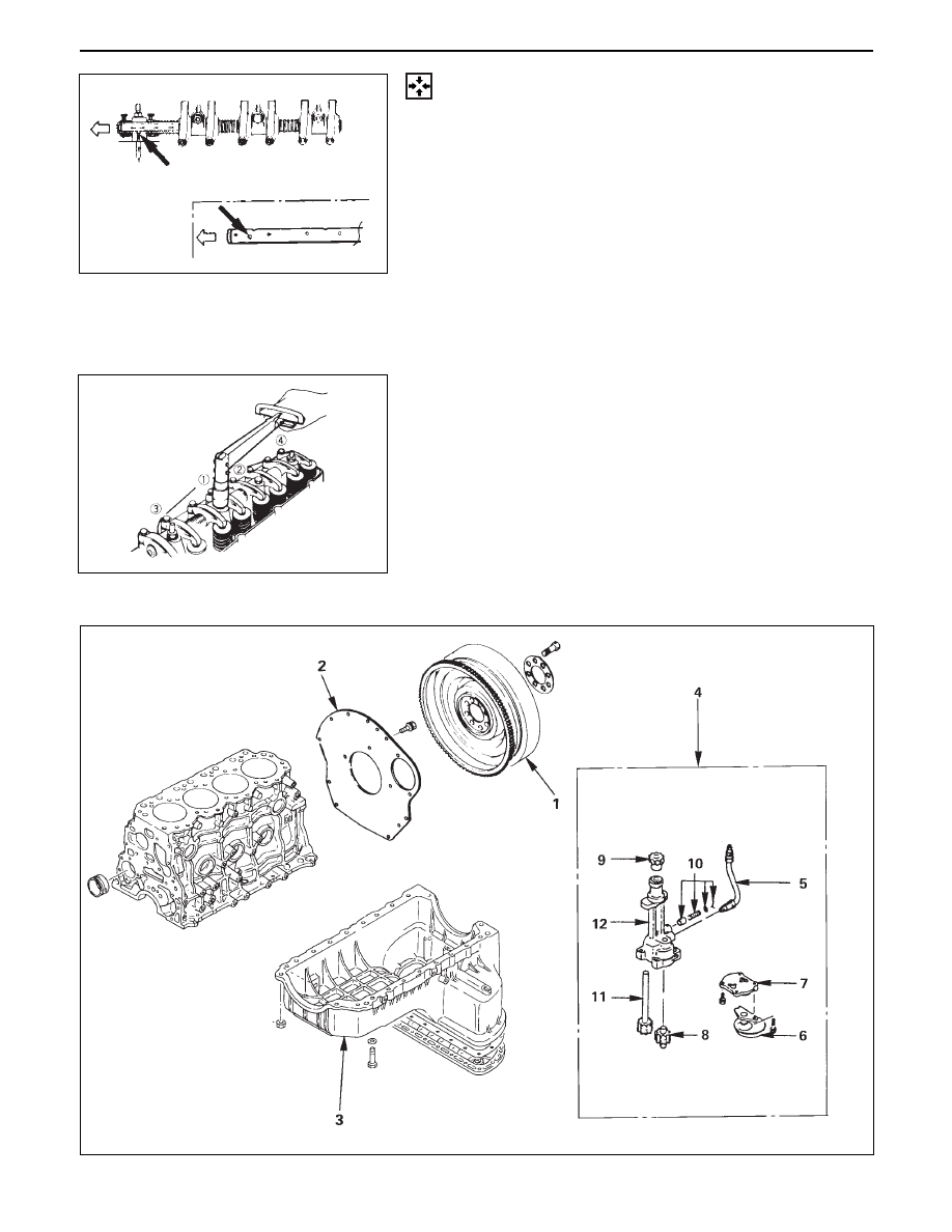
REASSEMBLY
7.
Rocker Arm Shaft
•
Apply a light coat of engine oil to the rocker arm
shafts.
•
Position the rocker arm shaft with the large oil
hole (4
φ
) facing the front of the engine.
•
Install the rocker shaft together with the rocker
arm, the rocker arm shaft bracket, and the spring.
6.
Rocker Arm Shaft Spring
5.
Rocker Arm
4.
Rocker Arm Shaft Bracket
3.
Rocker Arm
2.
Rocker Arm Shaft Snap Ring
1.
Rocker Arm Shaft Assembly
•
Install the rocker arm shaft assembly in cylinder
head.
•
Tighten the rocker arm shaft fixing bolts to the
specified torque.
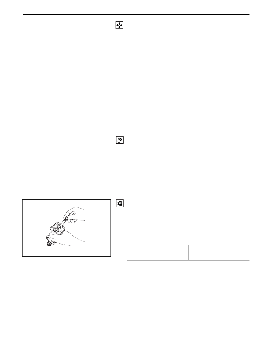
OIL PUMP
6A – 22 ENGINE MECHANICAL
DISASSEMBLY
1.
Flywheel
2.
Cylinder Block Rear Plate
3.
Crankcase Assembly
•
Refer to section 6A2 “Crankcase”.
4.
Oil Pump Assembly
5.
Oil Pipe
6.
Strainer Assembly
7.
Pump Cover
8.
Driven Gear
9.
Pinion Gear
10. Relief Valve
11. Drive Shaft
12. Oil Pump Body
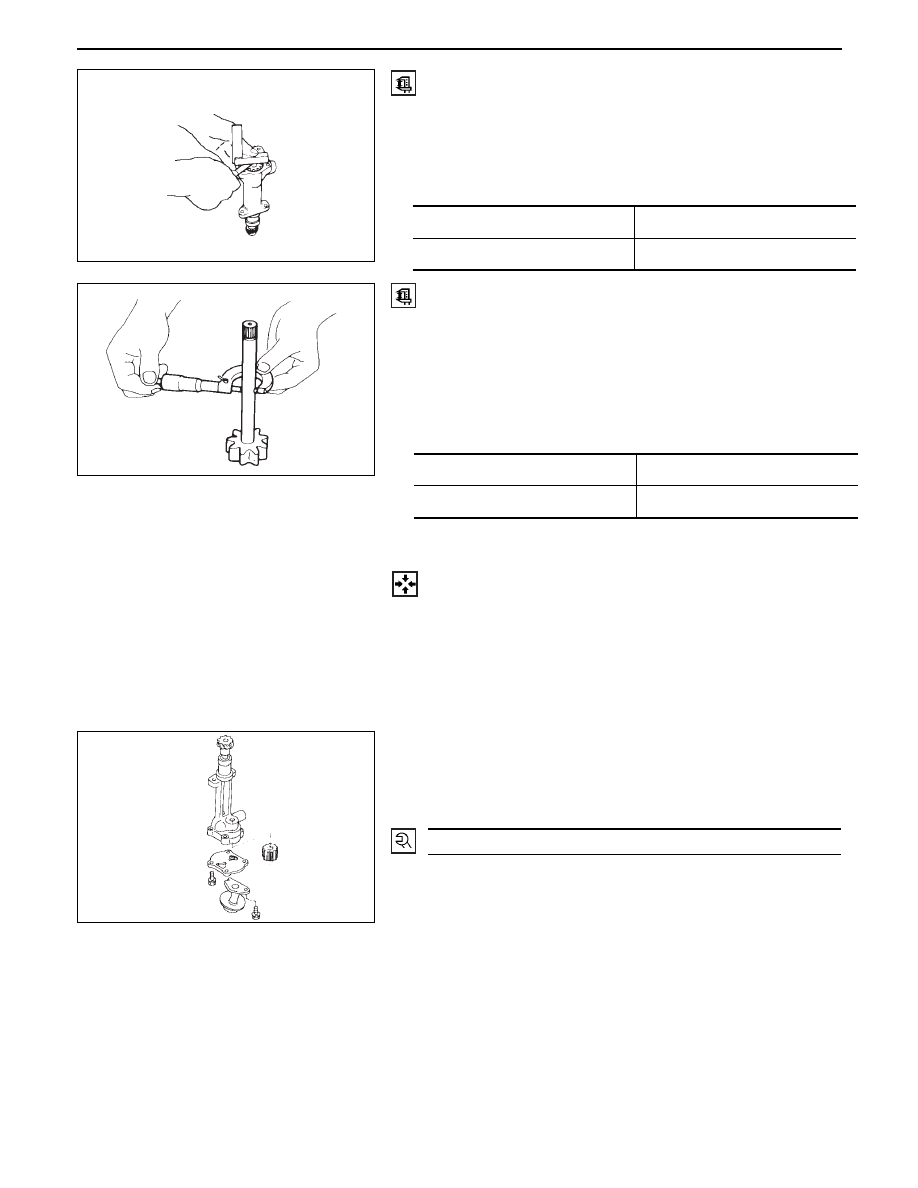
INSPECTION AND REPAIR
Make the necessary adjustments, repairs, and part placements if excessive wear or damage is discovered
during inspection.
Body and gears
The pump assembly must be replaced if one or more of
the conditions below is discovered during inspection.
•
Badly worn or damaged driven gear guide.
•
Badly worn or damaged gear teeth.
Gear Teeth and Body Inner Wall Clearance
•
Use a feeler gauge to measure the clearance between
the gear teeth and the body inner wall.
•
If the clearance between the gear teeth and the body
inner wall exceeds the specified limit, either the gear
or the body must be replaced.
Standard
Limit
mm(in)
0.14 (0.0055)
Gear Teeth and Body
Internal Wall Clearance
0.20 (0.0079)
ENGINE MECHANICAL 6A – 23
Drive Shaft and Oil Pump Body Clearance
•
Use a micrometer to measure the drive shaft outside
diameter.
•
Use an inside dial indicator to measure the pump
body inside diameter.
•
If the clearance between the drive shaft and the oil
pump body exceeds the specified limit, the oil pump
assembly must be replaced.
Gear and Body Clearance
•
Use a feeler gauge to measure the clearance between
the body and the gear.
•
If the clearance between the gear and the body
exceeds the specified limit, the body must be re-
placed.
Standard
Limit
mm(in)
0.06 (0.0024)
Gear and Body Clearance
0.15 (0.0059)
Standard
Limit
mm(in)
0.04 (0.0016)
Drive Shaft and Oil Pump Body Clearance
0.20 (0.0079)
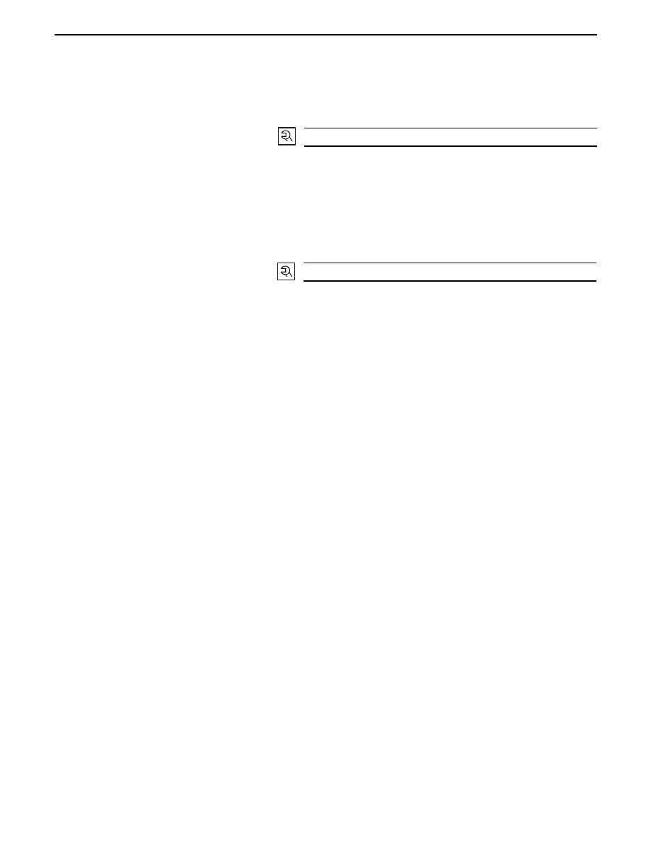
REASSEMBLY
12. Oil Pump Body
11. Drive Shaft
10. Relief Valve
9.
Pinion Gear
8.
Driven Gear
7.
Pump Cover
6.
Strainer Assembly
•
Install the strainer assembly and tighten the
strainer assembly fixing bolts.
5.
Oil Pipe
16 (1.6/12)
N·m(kg·m/lb·ft)
6A – 24 ENGINE MECHANICAL
4.
Oil Pump Assembly
•
Apply molybdenum mixed engine oil to drive
gear of camshaft and driven gear of oil pump.
•
Tighten the oil pump fixing bolt to the specified
torque
3.
Crankcase Assembly
•
Refer to Section 6A2 “Crankcase”.
2.
Cylinder Block Rear Plate
•
Align the rear plate with the cylinder body knock
pins. Tighten the rear plate to the specified
torque.
1.
Flywheel
•
Refer to Section 6A2 “Crankshaft and Main
Bearing”.
19 (1.9/14)
N·m(kg·m/lb·ft)
82 (8.4/61)
N·m(kg·m/lb·ft)
Нет комментариевНе стесняйтесь поделиться с нами вашим ценным мнением.
Текст