Opel Frontera UBS. Service manual — part 1268
ENGINE MECHANICAL 6A – 5
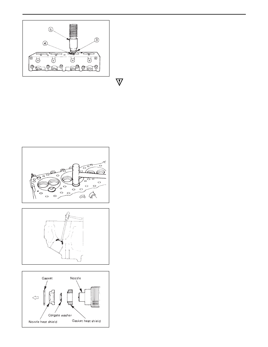
2.
Place an appropriate metal plate ➂ thick over the hot
plug upper surface ➃ .
3.
Use a press ➄ to exert a pressure of 44000-
54000N(4500 – 5500 kg) (9923 – 12128 lbs.) on the
metal plate covering the hot plug upper surface. This
will drive the hot plug into position.
4.
Lightly tap the hot plug heads to make sure that they
are firmly seated.
5.
Repeat the procedure Steps 1-4 for the remaining hot
plugs.
CAUTION:
Do not apply pressure greater than that specified. Dam-
age to the cylinder head will result.
6.
Use a surface grinder to grind off any hot plug sur-
face protuberances.
The hot plug surfaces must be perfectly flush with the
cylinder head.
7.
After grinding, make sure that the hot plug surfaces
are completely free of protuberances.
The hot plug surfaces must also be free of depres-
sions.
Once again, lightly tap the hot plug heads to make sure
that they are firmly seated.
Heat shield removal
After removing the hot plugs, use a hammer ➀ and a
brass bar ➁ to lightly tap the lower side of the heat
shiled ➂ and drive it free.
Heat shield installation
Install the heat shield washer and the heat shield to the
cylinder head from the nozzle holder installation hole
side. Lightly tap the flange into place with a brass bar.
The heat shield flange side must be facing up.
NOTE:
Always install a new heat shield. Never reuse the old
heat shield.
6A – 6 ENGINE MECHANICAL
REASSEMBLY
6.
Cylinder Head
•
Refer to Section 6A2 “Cylinder head”
5.
Push Rod
4.
Rocker Arm Shaft and Rocker Arm
•
Tighten rocker arm shaft fixing bolts
3.
Glow Plug and Glow Plug Connector
•
Tighten glow plugs.
2.
Injection Nozzle Holder
•
Refer to Section 6C2 “Injection nozzle”.
1.
Thermostat Housing Assembly
•
Tighten thermostat housing assembly fixing bolt
N·m (Kg·m/lb·ft)
54 (5.5/40)
N·m (Kg·m/lb·ft)
23 (2.3/17)
N·m (Kg·m/lb·ft)
19 (1.9/14)
ENGINE MECHANICAL 6A – 7
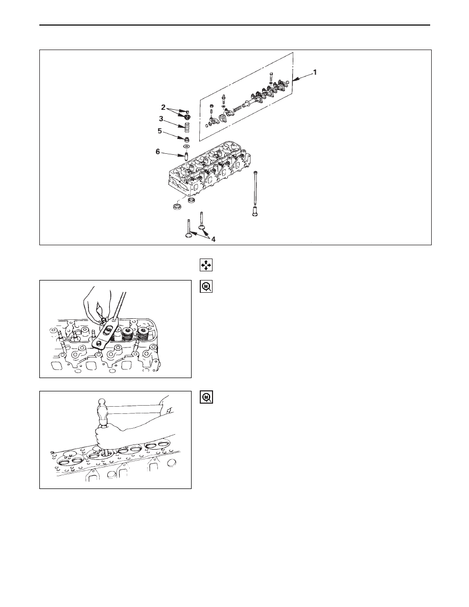
VALVE SPRING, VALVE STEM OIL SEAL, VALVE, VALVE GUIDE, PUSH ROD
DISASSEMBLY
1
Rocker Arm Asembly
2
Split Collar
Using special Tool, compress valve spring
Valve spring compressor: 9-8523-1423-0(J-29760)
3. Valve Spring
4. Valve
5. Valve Stem Oil Seal
6. Valve Guide
Valve Guide Replacer: 9-8523-1212-0
6A – 8 ENGINE MECHANICAL
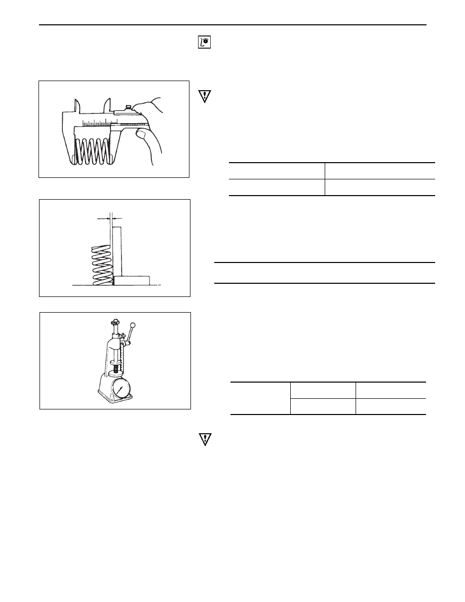
At installed
height 38.9mm
(1.5in)
Standard
N(Kg/lb)
Limit
294.0 (30/66.1)
257.9 (26.3/57.9)
Valve spring
CAUTION:
Visually inspect the valve springs and replace them if
damage or abnormal wear is evident.
1. Free height
•
Measure the free height of the springs. The springs
must be replaced if the height is below the specified
limit.
INSPECTION AND REPAIR
Make the necessary adjustments, repairs, and part replacements if excessive wear or damage is discovered
during inspection.
2. Squareness
•
Measure the valve spring squareness with a steel
square.
•
Replace the valve springs if the measured value
exceeds the specified limit.
3. Spring tension
•
Use a spring tester to compress the springs to the
installed height. Measure the compressed spring
tension.
Replace the springs if the measured tension is
below the specified limit.
Valve Guide
CAUTION:
Taking care not to damage the valve seat contact surface,
when removing carbon adhering to the valve head.
Carefully inspect the valve stem for scratching or
abnormal wear. If these conditions are present, the valve
and the valve guide must be replaced as a set.
Limit
mm(in)
1.7 (0.0669)
Standard
Limit
48.0 (1.8898)
47.100 (1.8543)
mm(in)
Нет комментариевНе стесняйтесь поделиться с нами вашим ценным мнением.
Текст