Opel Frontera UBS. Service manual — part 1179

6E–82
ENGINE DRIVEABILITY AND EMISSIONS
Engine Cranks But Will Not Run
(Cont'd)
Step
No
Yes
Value(s)
Action
13
1. Remove any ignition coil and install a spark tester at
the spark plug end of the coil.
2. Observe the tester while the engine is cranking.
Was a crisp, blue spark observed? Only one or two
sparks followed by no result is considered the same as
“No Spark.”
—
Go to
Step 15
Go to
Step 14
14
Replace the ignition coil, and return to Step 13 to test
the remaining coils.
Is the action complete?
—
Verify repair
—
15
Repeat Step 13 for each coil. Remove only one coil at a
time, and reinstall each coil on its spark plug after
testing, but do not refasten coils with screws at this
time.
After all coils have passed the spark test, does the
engine start?
—
Refasten all
coils with
their screws
Go to
Step 16
16
1. Remove the spark plugs from all cylinders.
2. Visually inspect the spark plug electrodes.
3. Replace any spark plugs with loose or missing
electrodes or cracked insulators.
Did your inspection reveal any spark plugs exhibiting
excessive fouling?
—
Correct the
fouling
condition
Go to
Step 17
17
Refer to
Engine Mechanical Diagnosis to diagnose the
following conditions:
D
Faulty or incorrect camshaft drive belts
D
Leaking or sticky valves or rings
D
Excessive valve deposits
D
Loose or worn rocker arms
D
Weak valve springs
D
Incorrect valve timing
D
Leaking head gasket
Is the action complete?
—
Verify repair
Go to
Step 19
18
Observe the “Engine Speed” data display on the scan
tool while cranking the engine.
Is the engine RPM indicated? (If the scan tool is
normally powered from the cigarette lighter socket, and
if the scan tool display goes blank while cranking the
engine, it will be necessary to power the scan tool
directly from the vehicle battery.)
—
Go to
Step 19
Go to
Step 28
19
1. Disconnect the 7-pin gray connector at the rear of
the air filter beneath the point where the air duct
attaches to the MAF sensor.
2. Ignition “ON.”
3. Using a test light connected to ground, probe the
ignition terminal at the PCM (female) side of the
7-pin connector.
Is the test light “ON?”
—
Go to
Step 20
Go to
Step 26

6E–83
ENGINE DRIVEABILITY AND EMISSIONS
Engine Cranks But Will Not Run
(Cont'd)
Step
No
Yes
Value(s)
Action
20
1. At the PCM (female) side of the connector, connect
a test light between the ignition + terminal and one
of the injector driver circuits at the same connector.
2. Ignition “ON.”
3. Observe the test light, and repeat the test for each
injector driver circuit.
Did the test light stay on when checking any of the 6
injector driver circuits?
—
Go to
Step 21
Go to
Step 23
21
1. Ignition “OFF,” disconnect the PCM.
2. Ignition “ON,” observe the test light.
Is the test light “ON?”
—
Go to
Step 22
Go to
Step 27
22
Locate and repair the short to ground in the injector
driver circuit.
Is the action complete?
—
Verify repair
—
23
1. Using the same test location as in step 20, connect
a test light between the ignition terminal and one of
the driver circuits.
2. Crank the engine and observe the test light.
3. Repeat for each injector driver circuit.
Did the light blink during the test for each circuit?
—
Go to
Step 25
Go to
Step 24
24
Check for an open injector driver circuit.
Was a problem found?
—
Verify repair
Go to
Step 27
25
1. At the injector (male) side of the gray connector,
connect an ohmmeter between the ignition pin and
one of the driver circuit pins.
2. Check for continuity in the circuit.
3. Repeat for each injector circuit. The readings
should be approximately equal to the specified
value for injector resistance.
Was a problem found?
12.5 ohms
Verify repair
Go to
Step 8
26
Repair the ignition feed circuit.
Is the action complete?
—
Verify repair
—
27
Replace the PCM.
IMPORTANT: The replacement PCM must be
programmed. Refer to
UBS 98model year Immobilizer
Workshop Manual.
Is the action complete?
—
Verify repair
—
28
1. Raise the vehicle and disconnect the CKP sensor
harness.
2. Ignition “ON.”
3. With a test light to ground, probe the harness
ignition feed terminal.
Did the light illuminate?
—
Go to
Step 30
Go to
Step 29
29
Check the ignition feed wire between the sensor and
the PCM for a short to ground or open circuit.
Is the action complete?
—
Verify repair
—

6E–84
ENGINE DRIVEABILITY AND EMISSIONS
Engine Cranks But Will Not Run
(Cont'd)
Step
No
Yes
Value(s)
Action
30
1. Ignition “ON.”
2. At the CKP harness connector, connect a test light
between the ignition and ground terminals.
Did the light illuminate?
—
Go to
Step 32
Go to
Step 31
31
Check the sensor ground circuit for an open or short to
voltage.
Is the action complete?
—
Verify repair
—
32
Check the signal circuit between the sensor and the
PCM for a short to ground, short to voltage, or an open.
Was a problem found?
—
Verify repair
Go to
Step 33
33
Replace the CKP sensor.
Is the action complete?
—
Verify repair
Go to
Step 27
6E–85
ENGINE DRIVEABILITY AND EMISSIONS
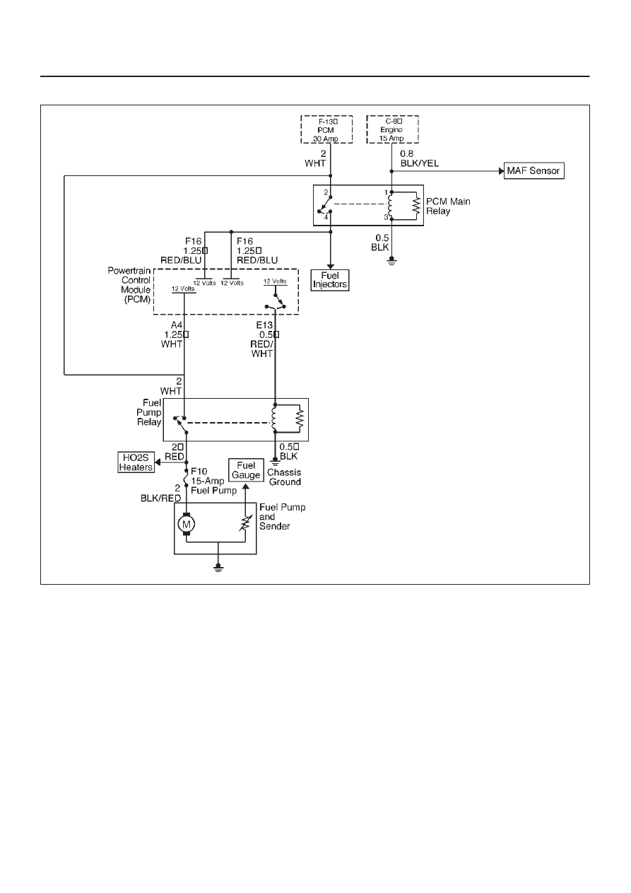
Fuel System Electrical Test
D06RW101
Circuit Description
When the ignition switch is first turned “ON,” the
powertrain control module (PCM) energizes the fuel
pump relay which applies power to the in-tank fuel pump.
The fuel pump relay will remain “ON” as long as the
engine is running or cranking and the PCM is receiving
58X crankshaft position pulses. If no 58X crankshaft
position pulses are present, the PCM de-energizes the
fuel pump relay within 2 seconds after the ignition is
turned “ON” or the engine is stopped.
The fuel pump delivers fuel to the fuel rail and injectors,
then to the fuel pressure regulator. The fuel pressure
regulator controls fuel pressure by allowing excess fuel to
be returned to the fuel tank. With the engine stopped and
ignition “ON,” the fuel pump can be turned “ON” by using a
command by Tech 2.
Diagnostic Aids
An intermittent may be caused by a poor connection,
rubbed-through wire insulation, or a wire broken inside
the insulation. Check for the following items:
D
Poor connection or damaged harness – Inspect the
PCM harness and connectors for improper mating,
broken locks, improperly formed or damaged
terminals, poor terminal-to-wire connection, and
damaged harness.
Test Description
Number(s) below refer to the step number(s) on the
Diagnostic Chart.
2. If the fuel pump is operating but incorrect pressure is
noted, the fuel pump wiring is OK and the “Fuel
System Pressure Test” chart should be used for
diagnosis.
Нет комментариевНе стесняйтесь поделиться с нами вашим ценным мнением.
Текст