Opel Frontera UBS. Service manual — part 1773
SECURITY AND LOCKS
8H–21
Rear Door Lock Actuator Installation
To install, follow the removal steps in the reverse order.
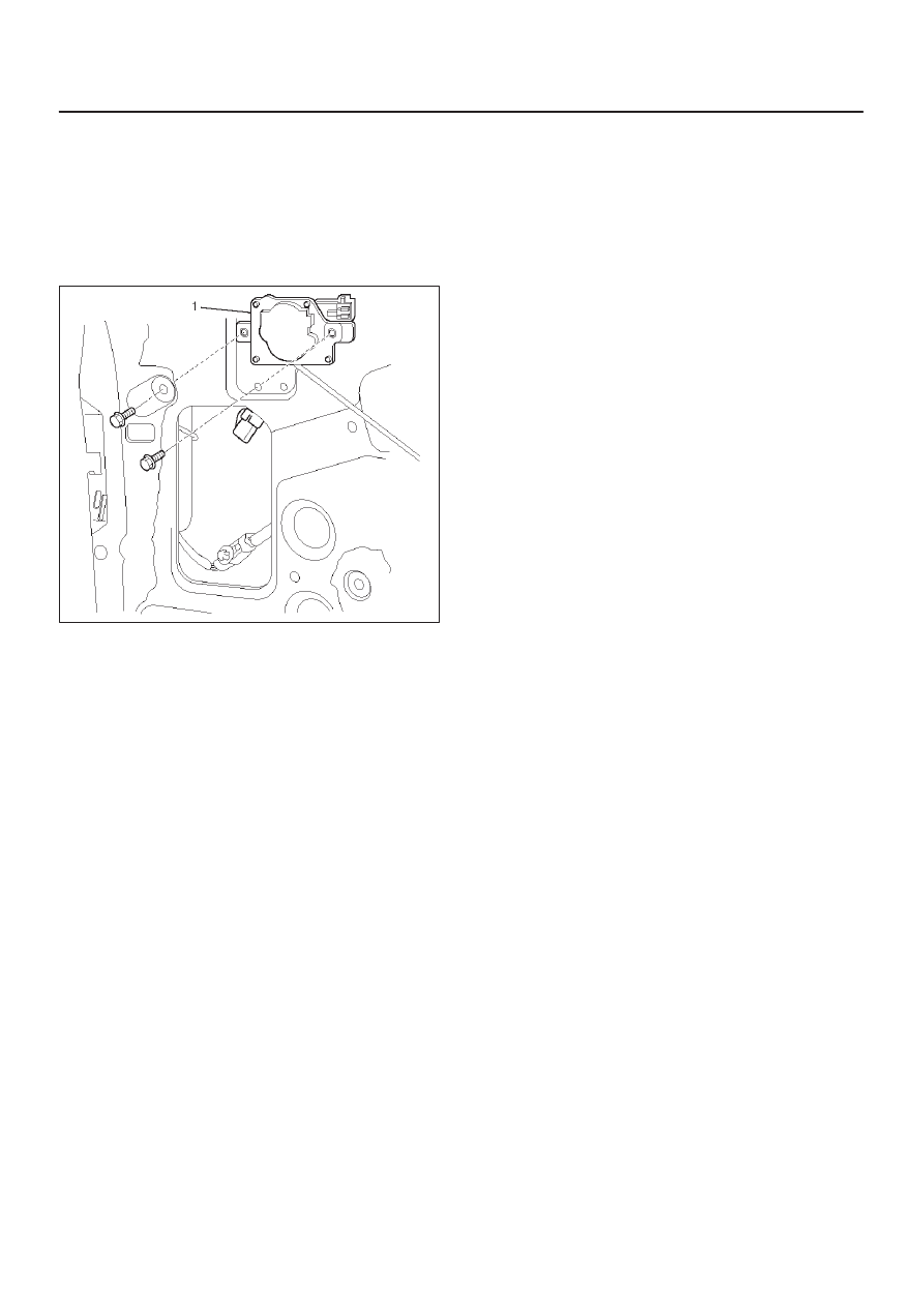
Tailgate Lock Actuator Removal
1. Refer to the Tailgate Lock Assembly removal
procedure in this section.
2. Remove the tailgate lock actuator(1).
632RY00002
Tailgate Lock Actuator Installation
To install, follow the removal steps in the reverse order.
8H–22 SECURITY AND LOCKS
Anti-theft System
General Description
The circuit consists of the starter switch, anti-theft &
keyless entry control unit, anti-theft horn, front door and
tailgate key switch (detect and tamper switch), door lock
(& power window) switch, door lock actuator for each
door, engine hood switch, clutch start switch (M/T),
ANTI-THEFT indicator light and mode switch (A/T).
The system operates as follows: After locking the starter
switch and removing the starter key (this sets the alarm),
if the door is unlocked in any way other than with the
proper key, the headlights start flashing, the horn sounds,
and the starter circuit is disabled. (However, the engine
hood and all the doors must be locked and closed.)
Once the system has been placed in the warning or alarm
condition, it can be released only when the starter switch
is shifted from “OFF” to “ACC” by the starter key, or when
the lock of the front door or the tailgate is released (to
activate the detect switch) by the starter key.
Anti-theft & Keyless Entry Control
Unit Removal
1. Disconnect the battery ground cable.
2. Remove the front console assembly.
D
Refer to the Instrument Panel Assembly in Body
Structure section.
3. Remove the lower cluster assembly.
D
Refer to the Instrument Panel Assembly in Body
Structure section.
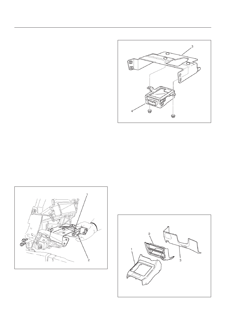
4. Disconnect the connector(2).
5. Remove four screws to remove the anti-theft &
keyless entry control unit with bracket(1).
825RW029
6. Remove two nuts from the anti-theft & keyless entry
control unit with bracket(3) to remove the anti-theft &
keyless entry controller(4).
825RW028
Anti-theft & Keyless Entry Control
Unit Installation
To install, follow the removal steps in the reverse order.
Anti-theft Indicator Removal
1. Disconnect the battery ground cable.
2. Remove the front console assembly(1).
D
Refer to the Instrument Panel Assembly in Body
Structure section.
3. Remove the lower cluster assembly(2).
D
Refer to the Instrument Panel Assembly in Body
Structure section.
4. Remove the instrument panel driver lower cover
assembly(3).
D
Refer to the Instrument Panel Assembly in Body
Structure section.
821RW024
SECURITY AND LOCKS
8H–23
5. Remove the instrument panel cluster assembly(4).
D
Refer to the Instrument Panel Assembly in Body
Structure section.
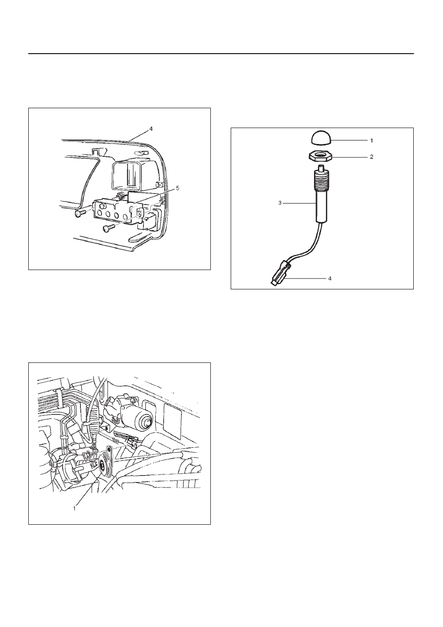
6. Remove two screws and then remove the anti-theft
indicator(5).
821RW032
Anti-theft Indicator Installation
To install, follow the removal steps in the reverse order.
Anti-theft Horn Removal
1. Disconnect the battery ground cable.
2. Disconnect the connector and remove the fixing bolt
to remove the anti-theft horn(1).
828RS007
Anti-Theft Horn Installation
To install, follow the removal steps in the reverse order.
Engine Hood Switch Removal
1. Disconnect the battery ground cable.
2. Remove the cap(1).
3. Remove the lock nut(2).
4. Disconnect the connector(4).
5. Remove the engine hood switch(3).
828RS011
Engine Hood Switch Installation
To install, follow the removal steps in the reverse order.

8H–24 SECURITY AND LOCKS
Keyless Entry System
ID Code Registration (Except South
Africa)
There are four kinds of ID codes which can be registered,
for which these two modes, ID code new registration and
ID code additional registration, are available.
ID Code New Registration
This procedure erases all registered ID codes and
registers a new received ID code instead.
Step
Action
Yes
No
1
1. Confirm that all the doors are closed and unlocked.
2. Open the driver’s side door.
3. Insert the key into the starter switch.
Is the action complete?
Go to Step 2
Go to Step 1
2
Turn the starter switch to ACC position and then to OFF position
three times.
NOTE: This step must be carried out within five seconds after
step 1.
Is the action complete?
Go to Step 3
Go to Step 1
3
Close the driver’s side door and then open it two times.
NOTE: This step must be carried out within ten seconds after
step 2.
Is the action complete?
Go to Step 4
Go to Step 1
4
1. Turn the starter switch to ACC position and then to OFF
position five times.
2. Close the driver’s side door and then open it.
NOTE: This step must be carried out within ten seconds after
step 3.
Is the action complete?
Go to Step 5
Go to Step 1
5
The control unit locks and unlocks the doors one time.
Does the control unit work normally?
Go to Step 6
Go to Step 1
6
Operate the lock or unlock button of the transmitter.
NOTE: This step must be carried out within twenty seconds
after step 5.
Is the action complete?
Go to Step 7
Go to Step 1
7
The control unit locks and unlocks the doors one time.
Does the control unit work normally?
Go to Step 8
Go to Step 1
8
Operate the lock or unlock button of the transmitter.
NOTE: This step must be carried out within twenty seconds
after step 7.
Is the action complete?
Go to Step 9
Go to Step 1
9
The control unit compares the two codes sent from the
transmitter.
If the code succeeds in registration, the control unit locks and
unlocks the doors one time.
If the two codes are different from each other or fails in
registration, the control unit locks and unlocks the doors three
times.
NOTE: In any case, this procedure is finished.
Go to Step 1
Go to Step 1
Нет комментариевНе стесняйтесь поделиться с нами вашим ценным мнением.
Текст