Opel Frontera UBS. Service manual — part 943
00 – 10 SERVICE INFORMATION
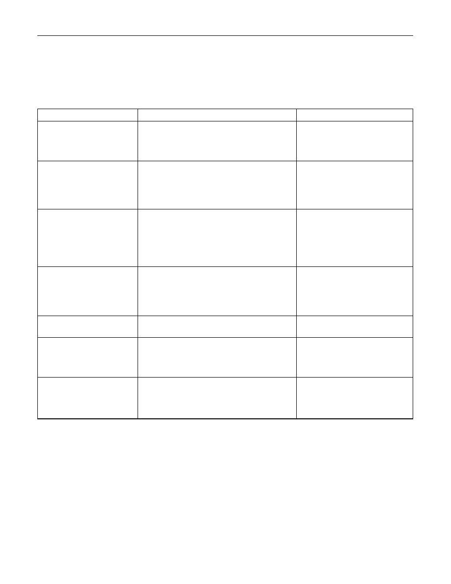
Problem
Possible Cause
Correction
STEERING COLUMN (CONT.)
TURN SIGNAL SWITCH
This troubleshooting covers mechanical problems only. See Section 8 for turn signal switch electrical
diagnosis.
Turn Signal Will Not Stay
in Turn Position
Turn Signal Will Not
Cancel
Turn Signal Difficult to
Operate
Turn Signal Will Not
Indicate Lane Change
Hezard Switch Cannot Be
Turned Off
No Turn Signal Lights
Front or Rear Turn Signal
Lights Not Flashing
1. Foreign material or loose parts
preventing movement of yoke.
2. Broken or missing detent or canceling
spring.
1. Loose switch mounting screws.
2. Switch or anchor bosses broken.
3. Broken, missing or out of position
detent, return or canceling spring.
4. Worn canceling cam.
1. Turn signal switch arm loose.
2. Yoke broken or distorted.
3. Loose or misplaced springs.
4. Foreign parts and/or material.
5. Loose turn signal switch mounting
screws.
1. Broken lane change pressure pad or
spring hanger.
2. Broken, missing or misplaced lane
change spring.
3. Base of wire damaged.
1. Foreign material between hazard
switch to turn signal switch body.
1. Electrical failure in chassis harness.
2. Inoperative turn signal flasher unit.
3. Loose chassis harness connector.
1. Burned-out damaged turn signal bulb.
2. High resistance connection to ground
at bulb socket.
3. Loose chassis harness connector.
Repair or replace signal switch.
Replace signal switch.
Tighten mounting screws.
Replace turn signal switch.
Replace turn signal switch.
Replace turn signal switch.
Tighten arm screw.
Replace turn signal switch.
Replace turn signal switch.
Repair turn signal switch.
Tighten mounting screws.
Replace turn signal switch.
Replace turn signal switch.
Replace turn signal switch.
Repair or replace hazard
switch.
Refer to Section 8 “Electrical
Troubleshooting”.
Replace flasher unit.
Repair loose connector.
Replace bulb.
Repair bulb socket.
Repair loose connector.
SERVICE INFORMATION 00 – 11
MAIN DATA AND SPECIFICATIONS
FRONT END ALIGNMENT
Caster
2° 10' ± 45'
Camber
0° ± 30'
King pin inclination
12° 30' ± 30'
Toe-in
mm (in)
0 ± 2 (0 ± 0.08)
Max. steering angle
(inside)
34°
+0°
(outside)
32°
+0°
–2°
POWER STEERING
Steering gear
Type
Integral, ball screw
Gear ratio
16.3 : 1
Oil pump
Type
Vane
Operating fluid
ATF DEXRON
®
-
Ⅱ E or Ⅲ

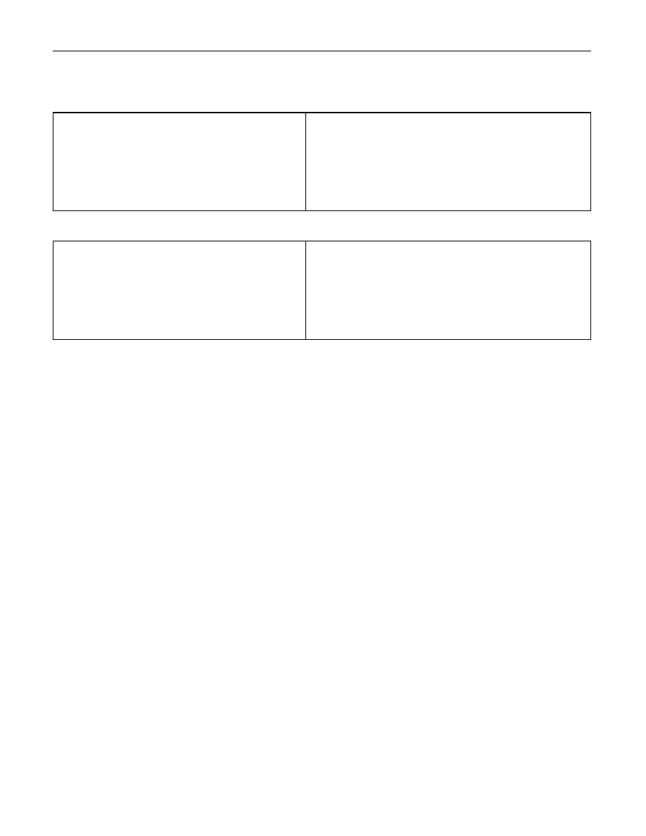
00 – 12 SERVICE INFORMATION
Items
Service Standard
Service Limit
SERVICE STANDARD
POWER STEERING GEAR
Sector shaft outside diameter
mm (in)
POWER STEERING PUMP
Fluid pressure
(When the engine is normal operating
temperature, increase engine speed to
1500rpm.)
kpa (kg/cm
2
/psi)
STEERING WHEEL
Free play
mm (in)
32.0 (1.26)
9300 – 9800
6VD1
(95 – 100 / 1350 – 1420)
(
6VE1
)
9800 – 10300
4JG2
(100 – 105 / 1420 – 1490)
(
4JX1
)
0 – 30 (0 – 1.18)
31.7 (1.25)
––––––––
––––––––

SERVICE INFORMATION 00 – 13
STEERING
INSPECTION
Visual check
Check the following parts:
•
Oil leakage.
•
Steering system for looseness or damage.
•
Steering function
•
Joint ball for oil leakage or damage.
•
Joint ball rubber boot for damage.
MAINTENANCE
The hydraulic system should be kept clean and fluid level
in the reservoir should be checked at regular intervals and
fluid added when required. Refer to "MAINTENANCE AND
LUBRICATION" in section 0B of the manual for type of
fluid to be used and intervals for filling.
If the system contains some dirt, flush it as detailed later
in this section. If it is exceptionally dirty, both the pump
and the gear must be completely disassembled before
further usage.
All tubes, hoses, and fittings should be inspected for
leakage at regular intervals. Fittings must be tight. Make
sure the clips, clamps and supporting tubes and hoses are
in place and properly secured.
Power steering hoses and lines must not be twisted,
kinked or tightly bent. Air in the system will cause spongy
action and noisy operation. When a hose is disconnected
or when fluid is lost, for any reason, the system must be
bled after refilling. Refer to "Bleeding the Power Steering
System" in this section.
FLUID LEVEL
1.
Run the engine until the power steering fluid reaches
normal operating temperature, about 55°C (130°F),
then shut the engine off.
2.
Check the level of fluid in the reservoir.
3.
If the fluid level is low, add power steering fluid as
specified in "MAINTENANCE AND LUBRICATION" in
section 0B to the proper level and install the receiver
cap.
4.
When checking the fluid level after the steering
system has been serviced, air must be bled from the
system. Refer to "Bleeding the Power Steering
System" in this section.
SERVICING
Нет комментариевНе стесняйтесь поделиться с нами вашим ценным мнением.
Текст