Opel Frontera UBS. Service manual — part 986
4A1–27
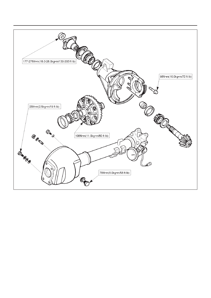
DIFFERENTIAL (FRONT)
E04RW015
DIFFERENTIAL (FRONT)
4A1–28
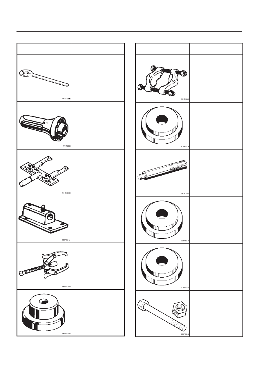
Special Tools
ILLUSTRATION
TOOL NO.
TOOL NAME
5–8840–2157–0
(J–37221)
Holder; Pinion flange
9–8522–1275–0
(J–24250)
Installer; Oil seal
5–8840–0275–0
(J–37264)
Differential holding
fixture
(Use with
5–8840–0003–0 base)
5–8840–0003–0
(J–3289–20)
Holding fixture base
5–8840–0013–0
5–8840–0014–0
(J–22888)
Puller; Side bearing
9–8521–1743–0
(J–8107–2)
Adapter; Side bearing
plug
ILLUSTRATION
TOOL NO.
TOOL NAME
5–8840–0015–0
(J–22912–01)
Separator
9–8522–1141–0
(J–24256)
Installer; Outer bearing
outer race
5–8840–0007–0
(J–8092)
Driver handle
9–8522–1274–0
(J–24252)
Installer; Inner bearing
outer race
5–8840–2085–0
(J–21777–42)
Pilot
5–8840–2089–0
(J–23597–9)
Nut and bolt
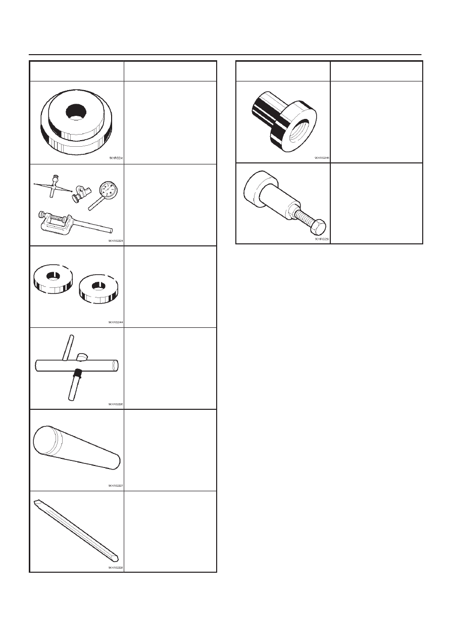
4A1–29
DIFFERENTIAL (FRONT)
ILLUSTRATION
TOOL NO.
TOOL NAME
5–8840–2087–0
(J–23597–7)
Gauge plate
5–8840–0126–0
(J–8001)
Dial indicator
5–8840–2088–0
(J–23597–8)
Disc
5–8840–0128–0
(J–23597–1)
Arbor
9–8522–1165–0
(J–6133–01)
Installer; Pinion bearing
5–8840–2293–0
(J–39209)
Punch; End nut lock
ILLUSTRATION
TOOL NO.
TOOL NAME
9–8522–1164–0
(J–24244)
Installer; Side bearing
5–8840–2323–0
(J–39602)
Remover; Outer bearing
DIFFERENTIAL (REAR 220mm)
4A2A–1
DRIVELINE/AXLE
DIFFERENTIAL (Rear 220mm)
CONTENTS
Service Precaution
4A2A–1
. . . . . . . . . . . . . . . . . . . . . .
General Description
4A2A–2
. . . . . . . . . . . . . . . . . . . . .
Diagnosis
4A2A–3
. . . . . . . . . . . . . . . . . . . . . . . . . . . . . .
Axle Housing
4A2A–4
. . . . . . . . . . . . . . . . . . . . . . . . . . .
Axle Housing and Associated Parts
4A2A–4
. . . . . .
Removal
4A2A–4
. . . . . . . . . . . . . . . . . . . . . . . . . . . . .
Oil Seal Replacement
4A2A–5
. . . . . . . . . . . . . . . . . .
Installation
4A2A–5
. . . . . . . . . . . . . . . . . . . . . . . . . . . .
Axle Shaft
4A2A–6
. . . . . . . . . . . . . . . . . . . . . . . . . . . . . .
Axle Shaft and Associated Parts
4A2A–6
. . . . . . . . .
Removal
4A2A–6
. . . . . . . . . . . . . . . . . . . . . . . . . . . . .
Inspection and Repair
4A2A–7
. . . . . . . . . . . . . . . . . .
Oil Seal Replacement
4A2A–8
. . . . . . . . . . . . . . . . . .
Installation
4A2A–8
. . . . . . . . . . . . . . . . . . . . . . . . . . . .
Pinion Oil Seal
4A2A–9
. . . . . . . . . . . . . . . . . . . . . . . . . .
Pinion Oil Seal and Associated Parts
4A2A–9
. . . . .
Removal
4A2A–9
. . . . . . . . . . . . . . . . . . . . . . . . . . . . .
Inspection and Repair
4A2A–10
. . . . . . . . . . . . . . . . . .
Installation
4A2A–10
. . . . . . . . . . . . . . . . . . . . . . . . . . . .
Differential Assembly
4A2A–11
. . . . . . . . . . . . . . . . . . . .
Differential Assembly and Associated Parts 4A2A–11
Removal
4A2A–11
. . . . . . . . . . . . . . . . . . . . . . . . . . . . .
Installation
4A2A–12
. . . . . . . . . . . . . . . . . . . . . . . . . . . .
Disassembled View
4A2A–13
. . . . . . . . . . . . . . . . . . . .
Disassembly
4A2A–14
. . . . . . . . . . . . . . . . . . . . . . . . . .
Reassembly
4A2A–16
. . . . . . . . . . . . . . . . . . . . . . . . . .
Differential Cage Assembly
4A2A–24
. . . . . . . . . . . . . . .
Disassembled View
4A2A–24
. . . . . . . . . . . . . . . . . . . .
Disassembly
4A2A–24
. . . . . . . . . . . . . . . . . . . . . . . . . .
Inspection and Repair
4A2A–25
. . . . . . . . . . . . . . . . . .
Reassembly
4A2A–26
. . . . . . . . . . . . . . . . . . . . . . . . . .
Limited Slip Differential
4A2A–28
. . . . . . . . . . . . . . . . . . .
Disassembled View
4A2A–28
. . . . . . . . . . . . . . . . . . . .
Disassembly
4A2A–29
. . . . . . . . . . . . . . . . . . . . . . . . . .
Inspection and Repair
4A2A–29
. . . . . . . . . . . . . . . . . .
Reassembly
4A2A–31
. . . . . . . . . . . . . . . . . . . . . . . . . .
Main Data and Specifications
4A2A–35
. . . . . . . . . . .
Special Tools
4A2A–37
. . . . . . . . . . . . . . . . . . . . . . . . . .
Service Precaution
WARNING: IF SO EQUIPPED WITH A
SUPPLEMENTAL RESTRAINT SYSTEM (SRS),
REFER TO THE SRS COMPONENT AND WIRING
LOCATION VIEW IN ORDER TO DETERMINE
WHETHER YOU ARE PERFORMING SERVICE ON OR
NEAR THE SRS COMPONENTS OR THE SRS
WIRING. WHEN YOU ARE REFORMING SERVICE ON
OR NEAR THE SRS COMPONENTS OR THE SRS
WIRING, REFER TO THE SRS SERVICE
INFORMATION. FAILURE TO FOLLOW WARNINGS
COULD RESULT IN POSSIBLE AIR BAG
DEPLOYMENT, PERSONAL INJURY, OR
OTHERWISE UNNEEDED SRS SYSTEM REPAIRS.
CAUTION: Always use the correct fastener in the
proper location. When you replace a fastener, use
ONLY the exact part number for that application.
ISUZU will call out those fasteners that require a
replacement after removal. ISUZU will also call out
the fasteners that require thread lockers or thread
sealant. UNLESS OTHERWISE SPECIFIED , do not
use supplemental coatings (Paints, greases, or other
corrosion inhibitors) on threaded fasteners or
fastener joint interfaces. Generally,such coatings
adversely affect the fastener torque and the joint
clamping force, and may damage the fastener. When
you install fasteners, use the correct tightening
sequence and specification. Following these
instructions can help you avoid damage to parts and
systems.
Нет комментариевНе стесняйтесь поделиться с нами вашим ценным мнением.
Текст