Opel Frontera UBS. Service manual — part 1911
SUPPLEMENTAL RESTRAINT SYSTEM STEERING WHEEL & COLUMN 2A – 69
STEERING COLUMN REPLACEMENT
4 3 1 R T
対米 Sec.3 F4
資料区分
品名 又は
電装タイトル
ユニットタイプ
いすゞ品番
J−No.
イラスト番号・追番
B K T G S
イラスト区分
資料番号(Pub.No.)
W O Y T
12
10
9
8
7
5
6
11
2
13
4
3
1
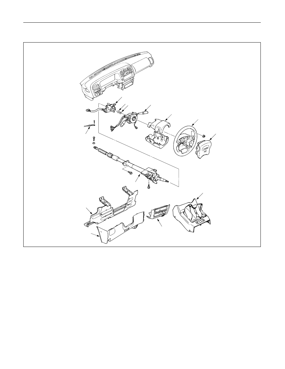
Removal Steps
1. Front console assembly
2. Lower cluster assembly
3. Steering lower cover
4. Driver knee bolster (rein-
forcement)
5. Inflator module
6. Steering wheel
7. Steering column cover
8. Combination switch and
SRS coil assembly
9. Snap ring
10. Cushion rubber
11. Shift lock cable (for A/T)
12. Lock cylinder assembly
13. Steering column assembly
Installation Steps
13. Steering column assembly
12. Lock cylinder assembly
11. Shift lock cable (for A/T)
10. Cushion rubber
9. Snap ring
8. Combination switch and
SRS coil assembly
7. Steering column cover
6. Steering wheel
5. Inflator module
4. Driver knee bolster (reinforcement)
3. Steering lower cover
2. Lower cluster assembly
1. Front console assembly
431RT002
These steps are based on the LHD model.
12
8
7
6
5
13
11
10
9
4
2
1
2A – 70 SUPPLEMENTAL RESTRAINT SYSTEM STEERING WHEEL & COLUMN
REMOVAL
Preparation:
1) Turn the steering wheel so that the vehicle's wheels
are pointing straight ahead.
2) Turn the ignition switch to "LOCK".
3) Disconnect the battery ground cable, and wait at least
5 minutes.
4) Disconnect the yellow 2way SRS connector located
under the steering column.
CAUTION:
The wheels of the vehicle must be straight ahead and the
steering column in the "LOCK" position before
disconnecting the steering wheel.
Failure to do so will cause the SRS coil assembly to
become uncentered which will cause damage to the SRS
coil assembly.
1. Front Console Assembly
Disconnect the transmission (for M/T) and transfer
control lever knob.
Disconnect the wiring harness connectors.
2. Lower Cluster Assembly
3. Steering Lower Cover
Remove the engine hood opening lever.
4. Driver Knee Bolster (Reinforcement)
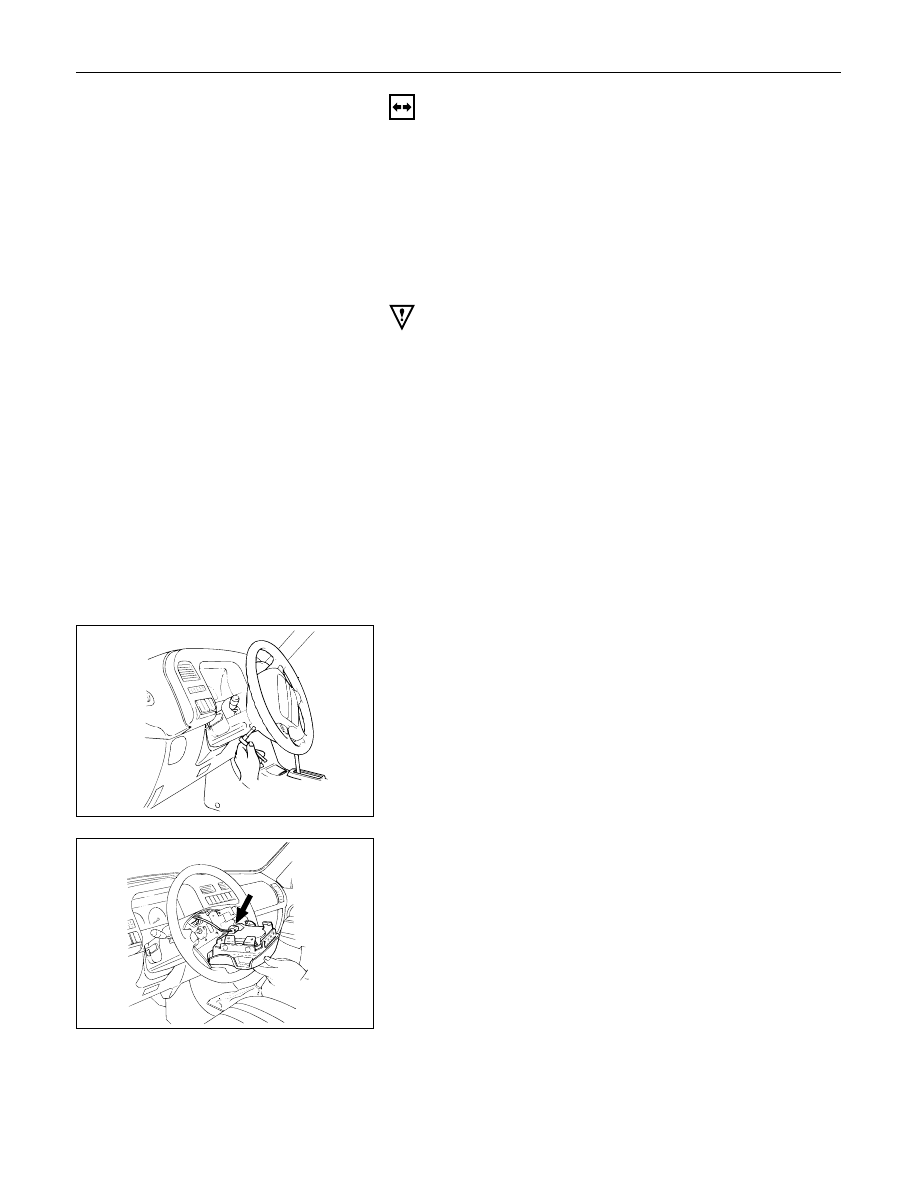
5. Inflator Module
1) Loosen the inflator module fixing bolt from
behind the steering wheel assembly using a
TORX
driver or equivalent until the inflator
module can be released from steering assembly.
2) Disconnect the yellow 2way SRS connector
located behind the inflator module.
827RS014
827RS015
SUPPLEMENTAL RESTRAINT SYSTEM STEERING WHEEL & COLUMN 2A – 71
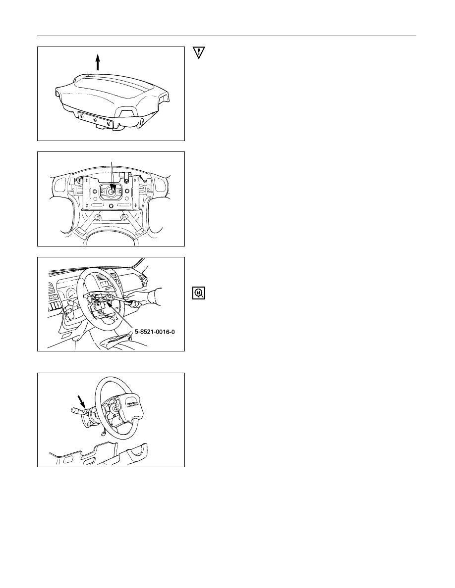
WARNING
THE INFLATOR MODULE SHOULD ALWAYS BE CARRIED
WITH THE URETHANE COVER AWAY FROM YOUR BODY
AND SHOULD ALWAYS BE LAID ON A FLAT SURFACE
WITH THE URETHANE SIDE UP. THIS IS NECESSARY
BECAUSE A FREE SPACE IS PROVIDED TO ALLOW THE
AIR CUSHION TO EXPAND IN THE UNLIKELY EVENT OF A
ACCIDENTAL DEPLOYMENT. OTHERWISE, PERSONAL
INJURY MAY RESULT.
6. Steering Wheel
Apply a setting mark across the steering wheel and
shaft so parts can be reassembled in their original
position.
Use special tool. Remove the steering wheel.
Move the tires to the straight ahead position before
removing the steering wheel.
Steering wheel remover: 5-8840-0016-0 (J-29752)
7. Steering Column Cover
8. Combination Switch and SRS Coil Assembly
1) Disconnect the wiring harness connectors
located under the steering column.
2) Remove the combination switch assembly with
SRS coil.
NOTE:
The SRS coil is a part of the combination switch
assembly, which can not be replaced separately.
Therefore, be sure not to remove the SRS coil from
the combination switch assembly.
9. Snap Ring
10. Cushion Rubber
11. Shift Lock Cable (for A/T)
12. Lock Cylinder Assembly
Disconnect the starter switch harness connector
located under the steering column.
827RS016
825RS046
Up
430RS004
Setting mark
2A – 72 SUPPLEMENTAL RESTRAINT SYSTEM STEERING WHEEL & COLUMN
Setting mark
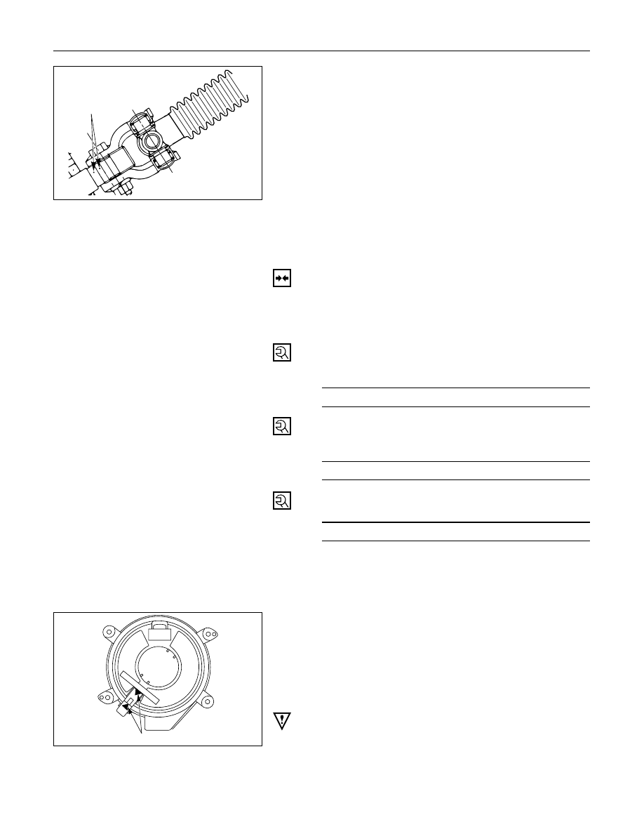
13. Steering Column Assembly
Apply a setting mark across the universal joint and
steering shaft to reassemble the parts in their original
position.
NOTE:
A setting mark can be easily made if the shaft is
withdrawn a little by loosening the steering shaft
universal joint.
431RV003
INSTALLATION
13. Steering Column Assembly
Align the setting marks on the universal joint and
steering shaft made during removal.
Tighten the steering column fixing bolt (dash panel)
to the specified torque.
Steering Column Bolt Torque
N·m (kg·m/lb·ft)
19 (1.9 / 14)
Tighten the steering column fixing bolt (pedal
bracket) to the specified torque.
Steering Column Bolt Torque
N·m (kg·m/lb·ft)
17 (1.7 / 13)
Tighten the universal joint to the specified torque.
Universal Joint Torque
N·m (kg·m/lb·ft)
25 (2.5 / 18)
12. Lock Cylinder Assembly
11. Shift Lock Cable (for A/T)
10. Cushion Rubber
9. Snap Ring
8. Combination Switch
1)
After installation of combination switch
assembly, connect the combination switch
wiring harness connector and the SRS 2way
connector located under the steering column.
2)
Turn the SRS coil counterclockwise to full, return
about 3 turns and align the neutral mark.
CAUTION:
When turning the SRS coil counterclockwise to full, stop
turning if resistance is felt. Forced further turning may
damage to the cable in the SRS coil.
Alignment mark
826RW027
Нет комментариевНе стесняйтесь поделиться с нами вашим ценным мнением.
Текст