Opel Frontera UBS. Service manual — part 1952
DIFFERENTIAL (REAR 244mm) 4A2B–31
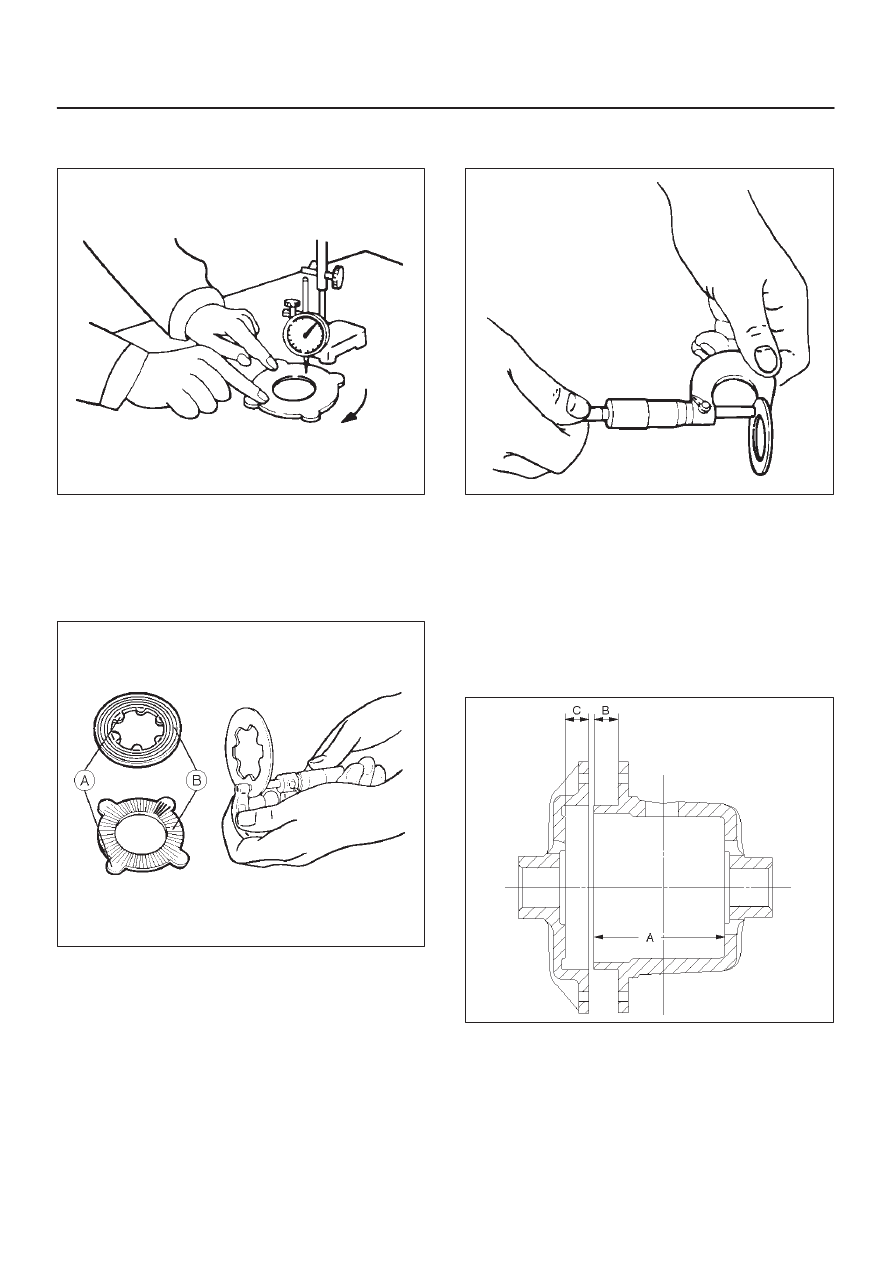
Measure the Deformation of the friction disc & plate.
Limit: 0.1 mm (0.004 in)
425RS061
Measure the wear of the friction plate & disc
Limit(A–B): 0.1 mm (0.004 in)
Remarks:
A=Inner or outer projections
B=Sliding surface subjected to abrasion
425RS062
Measure the wear of the thrust washer
Limit: 1.3 mm (0.05 in)
425RS063
Reassembly
Adjust the clearance between the friction disc and plate.
1. Measuring the depth of the differential cage.
Standard (A–B):
89.13 mm (3.51 in)
(C):
9.13 mm (0.36 in)
425RS064
4A2B–32
DIFFERENTIAL (REAR 244mm)
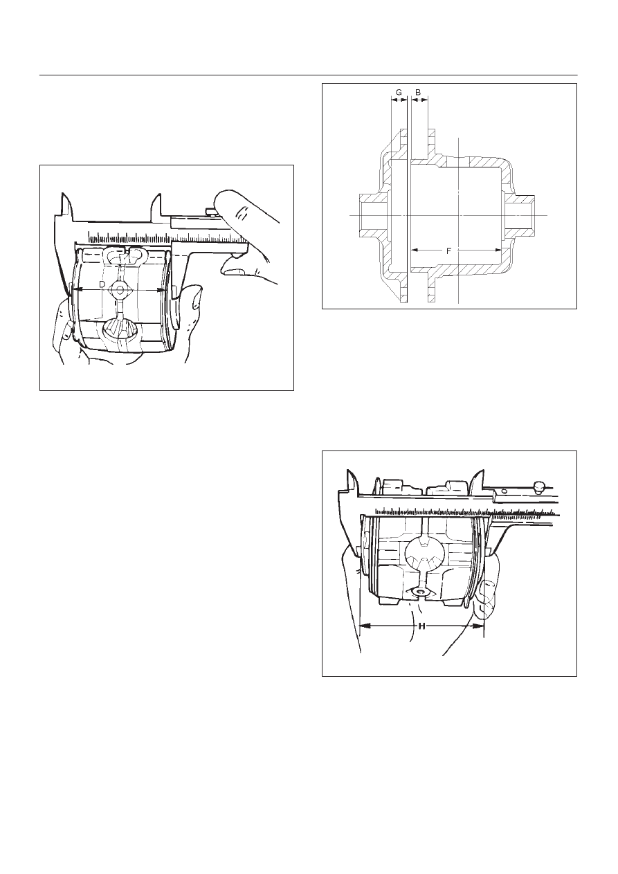
2. Measuring the overall length of the pressurering,
friction disc and friction plate.
D
Mount the pinion shaft in the pressurering and then
install the friction disc & plate.
D
Measure the length between the plates over the
V–groove. (D)
425RS065
3. After measuring dimensions A,B,C and D, make
adjustment in the following manner:
D
Measure the thickness (E) of the spring disc.
1.75mm (0.069in)
×
2 discs
4. Select the friction disc & plate so as to satisfy the
following equation:
{(A-B)+C}-(D+E)=0.06-0.20mm (0.002-0.008in)
Also, the total size difference of the friction disc &
plate and spring disc should be 0.05mm (0.02in) or
less.
Thickness
:1.65–1.75–1.85mm(0.065–0.069–0.073 in)
Backlash adjustment of the side gear in
the direction of the shaft
1. Measuring the depth of the differential cage.
(F–B): 95.63 mm (3.76 in)
(G): 15.63 mm (0.62 in)
425RS066
2. Measuring the dimension between the thrust washers
at both ends.
D
Assemble the side gear, pinion, pinion shaft,
pressure ring and thrust washer, and pressing the
pressure ring to–the pinion shaft in the direction of
the shaft to make the clearance 0.
D
Have the side gear contact to the pinion to make the
backlash 0.
D
Measure the dimension (H) between thrust
washers at both ends.
425RS067
DIFFERENTIAL (REAR 244mm) 4A2B–33
3. After measuring dimensions of each of the above
sections, proceed with the adjustment in the following
manner:
Adjust the clearance to satisfy the equation below.
{(F – B) + G – H}=0.05 – 0.20 mm
Also, select the thrust washers so that the
dimensional difference between the back surfaces of
the left and right pressure rings to the thrust washers
is 0.05mm or less.
Thickness :
1.5mm (0.059 in)
1.6 mm(0.063 in)
1.7 mm(0.067 in)
NOTE: When assembling the parts, apply recommended
gear oil sufficiently to each of the parts, especially, to the
contact surfaces and sliding surfaces.
1. Install Differential cage B.
2. Install Thrust washer.
3. Install Spring disc.
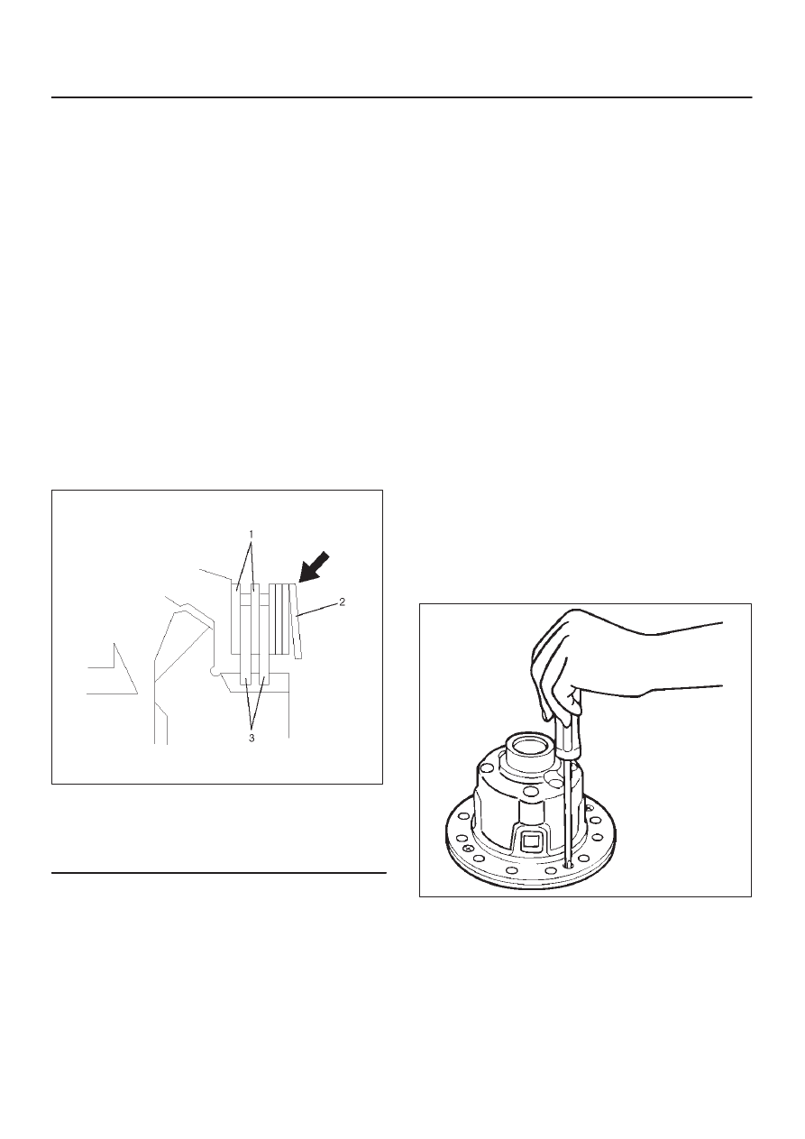
D
When assembling the spring disc, make sure the
mounting direction is correct as shown in figure.
425RY004
Legend
(1) Friction Plate
(2) Spring Disc
(3) Friction Disc
4. Install Friction disc.
5. Install Friction plate.
6. Install Friction plate.
7. Install Friction disc.
8. Install Friction plate.
9. Install Friction disc.
10. Install Friction plate.
11. Install Pressure ring.
12. Install Side gear.
13. Install Pinion and pinion shaft.
14. Install Side gear.
15. Install Pressure ring.
16. Install Friction plate.
17. Install Friction disc.
18. Install Friction plate.
19. Install Friction disc.
20. Install Friction plate.
21. Install Friction plate.
22. Install Friction plate.
23. Install Spring disc.
D
When assembling the spring disc, make sure the
mounting direction is correct.
24. Install Spring disc.
25. Install Thrust washer.
26. Install Differential cage A.
27. Install Screw.
D
Matching the guide marks of the differential cages A
and B, tighten the screws evenly in the diagonal
order.
425RS055
4A2B–34
DIFFERENTIAL (REAR 244mm)
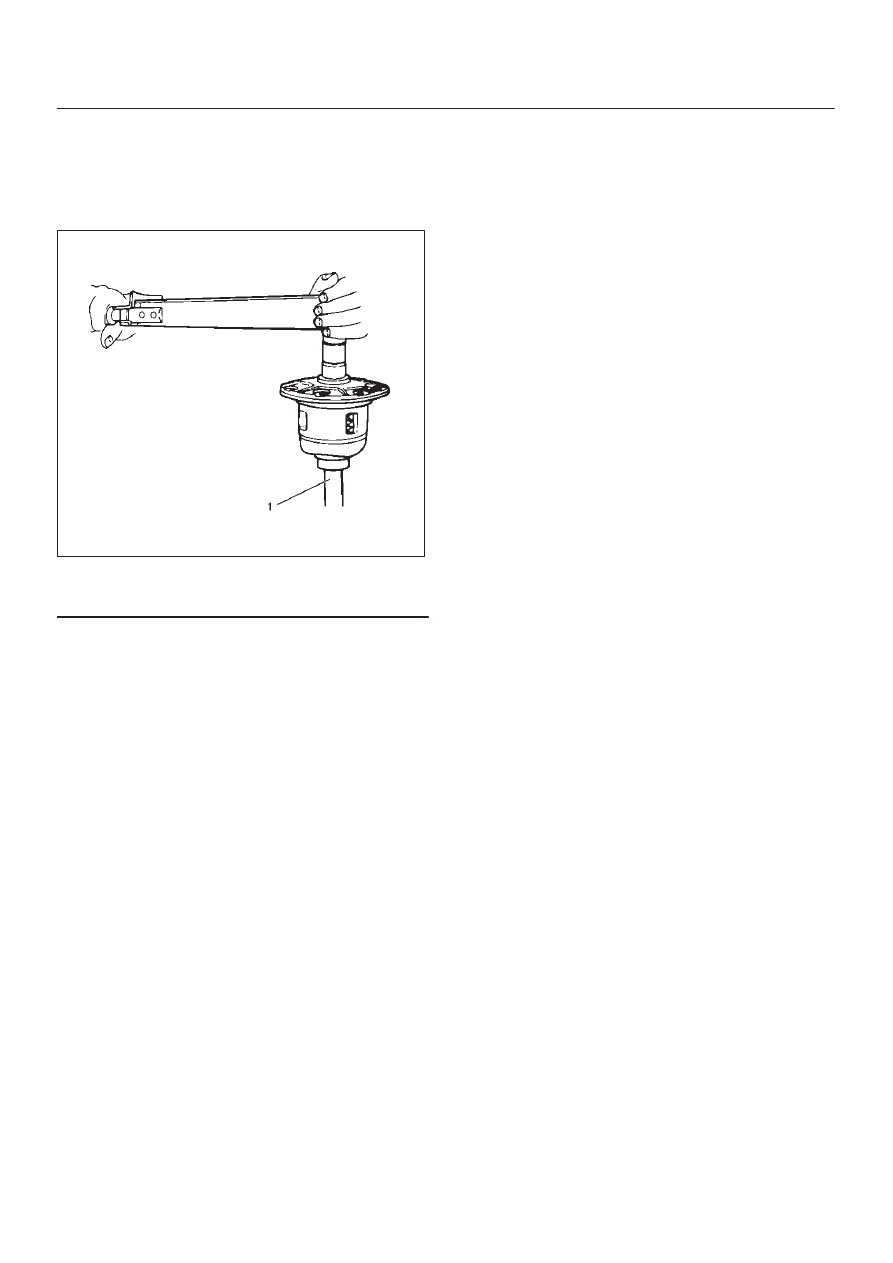
28. Check the operation.
D
Measure the starting torque using the side gear
holder.
Starting torque:
29 – 45 N·m (3.0 – 4.6 kg·m/ 22 – 33Ib ft)
425RW065
Legend
(1) Side Gear Holder : 5–8840–2381–0
Нет комментариевНе стесняйтесь поделиться с нами вашим ценным мнением.
Текст