Opel Frontera UBS. Service manual — part 906
1B – 18 AIR CONDITIONING
CHARGING THE REFRIGERANT SYSTEM
There are various methods of charging refrigerant into the
air conditioning system.
These include using ACR
4
(HFC-134a Refrigerant
Recovery/ Recycling/ Recharging/ System) or equivalent
and direct charging with a manifold gauge charging
station.
ACR
4
(115V 60Hz) : 5-8840-0629-0 (J-39500-A)
ACR
4
(220-240V 50/60Hz)
: 5-8840-0630-0 (J-39500-220A)
ACR
4
(220-240V 50/60Hz Australian model)
: 5-8840-0631-0 (J-39500-220ANZ)
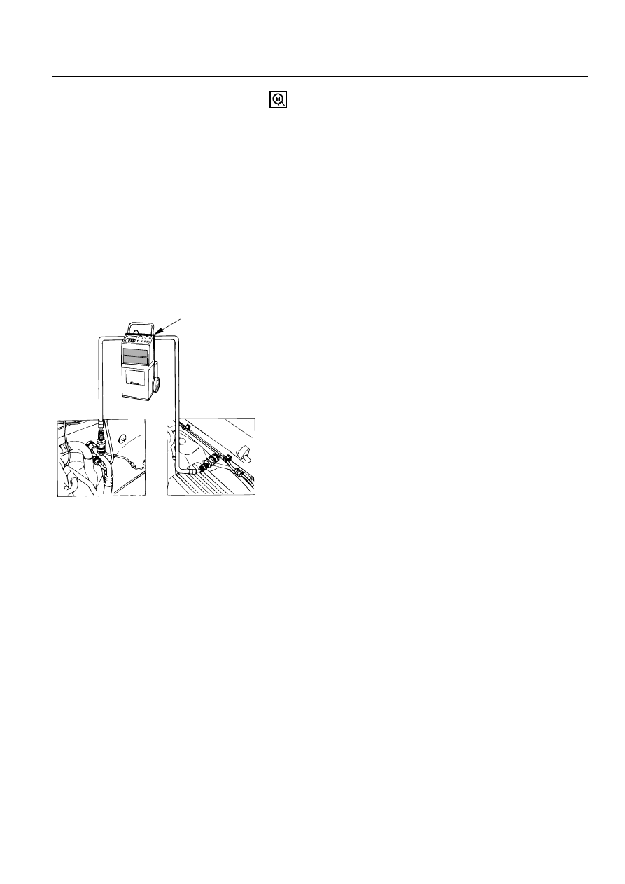
Charging procedure
•
ACR
4
(or equivalent) method
For the charging of refrigerant recovery by ACR
4
, follow
the manufacture’s instruction.
ACR
4
(Low side)
(High side)
HFC 134a
AIR CONDITIONING 1B – 19
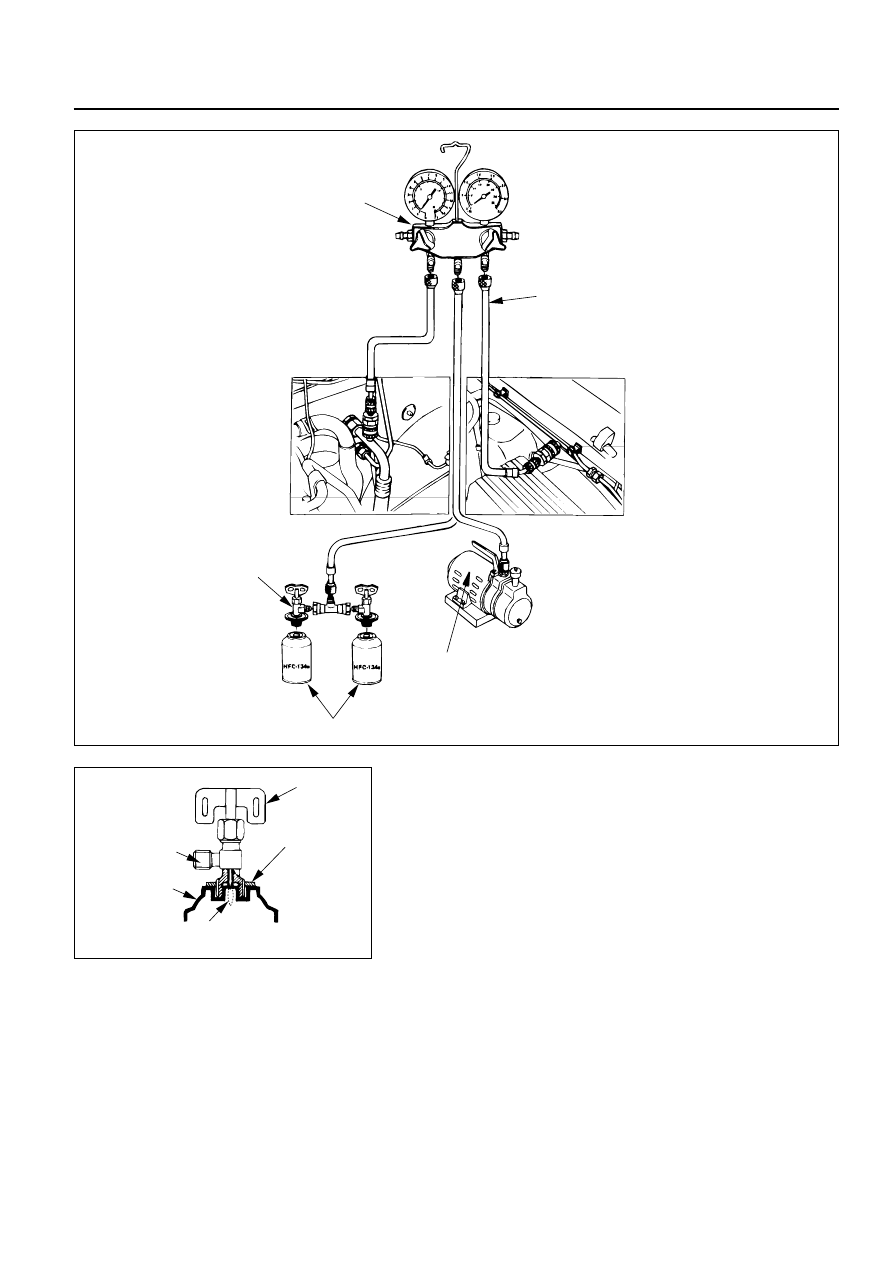
•
Direct charging with a manifold gauge charging station
method
Handling the charging valve handle when installing
refrigerant container.
1)
Before attaching the charge valve to the refrigerant
container, turn the charge valve handle
counterclockwise until the needle is fully retracted.
2)
Turn the plate nut counterclockwise until it reaches its
highest position relative to the charge valve.
3)
Install the charge valve onto the refrigerant container.
4)
Turn the plate nut clockwise and connect the center
hose of the manifold gauge to the charge valve.
5)
Tighten the plate nut sufficiently by hand. Then turn
the charge valve handle clockwise to lower the needle
and bore a hole in the refrigerant container.
6)
Turn the charge valve handle counterclockwise to
raise the needle. The refrigerant in the refrigerant
container is charged into the air conditioning system
by the operation of the manifold gauge.
•
Be absolutely sure not to reuse the emptied
refrigerant container.
Charge valve handle
Plate nut
Needle
Connection
<Charge valve>
Refrigerant container
Charging hose
Manifold gauge
Vacuum pump
Refrigerant container
Charge valve handle
(Low side)
(High side)

1B – 20 AIR CONDITIONING
1)
Make sure the evacuation process is correctly
completed.
2)
Connect the center-hose of the manifold gauge to the
refrigerant container.
•
Turn the charge valve handle counterclockwise to
purge the charging line and purge any air existing
in the center-hose of the manifold gauge.
3)
Open the low-pressure hand valve and charge the
refrigerant about 200 g(0.44 lbs.).
•
Make sure the high-pressure hand valve is closed.
•
Avoid charging the refrigerant by turning the
refrigerant container upside down.
4)
Close the low-pressure hand valve of the manifold
gauge.
•
Check to ensure that the degree of pressure does
not charge.
5)
Check the refrigerant leaks by using a HFC-134a leak
detector.
•
If a leak occurs, repair the leak connection, and
start all over again from the first step of
evacuation.
6)
If no leaks are found, open the low-pressure hand
valve of the manifold gauge.Then continue charging
refrigerant to the system.
•
When charging the system becomes difficult:
(1) Run the engine at Idling and close the all
vehicle doors.
(2) A/C switch is “ON”.
(3) Set the fan control knob (fan switch) to its
highest position.
WARNING
BE ABSOLUTELY SURE NOT TO OPEN THE HIGH-
PRESSURE HAND VALVE. SHOULD THE HIGH-
PRESSURE HAND VALVE BE OPENED, THE HIGH-
PRESSURE REFRIGERANT GAS WOULD FLOW
BACKWARD, AND THIS MAY CAUSE THE
REFRIGERANT CONTAINER TO BURST.
7)
When the refrigerant container is emptied, use the
following procedure to replace it with a new
refrigerant container.
(1) Close the low pressure hand valve.
(2) Raise the needle upward and remove the charge
valve.
(3) Reinstall the charge valve to the new refrigerant
container.
(4) Purge any air existing in the center hose of the
manifold gauge.

AIR CONDITIONING 1B – 21
8)
Charge the system to the specified amount and then
close the low-pressure hand valve.
Refrigerant Amount
g(lbs.)
750 (1.65)
DELPH1HD6/HT6
g(lbs.)
600 (1.32)
•
A fully charged system is indicated by the sight
glass on the receiver/driver being free of any
bubbles(Refer to “Reading Sight Glass”).
•
Check the high and low pressure value of the
manifold gauge.
•
Check for refrigerant leaks by using a HFC-134a
leak detector.
Immediately after charging refrigerant, both high and low
pressures are slightly high and to the left of the gauge, but
they settle down to the guide pressure valves as shown
below:
•
Ambient temperature; 25
∼
30°C (77
∼
86°F)
•
Guide pressure
High-pressure side;
Approx. 1373 – 1863 kPa (14 – 19 kg·cm
2
/ 199 – 270 PSI)
Low-pressure side;
Approx. 147 – 294 kPa (1.4 – 3.0 kg·cm
2
/ 21 – 43 PSI)
9)
Close the low pressure hand valve and charge valve
of the refrigerant container.
10) Stop the air conditioning and the engine.
11) Disconnect the high and low pressure hoses from the
manifold gauge fittings.
Нет комментариевНе стесняйтесь поделиться с нами вашим ценным мнением.
Текст