Opel Frontera UBS. Service manual — part 1413
6H – 2 ENGINE SPEED CONTROL
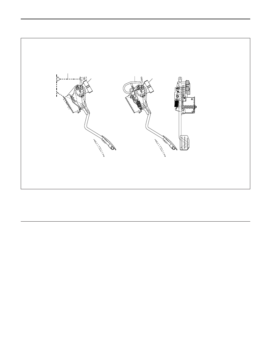
GENERAL DESCRIPTION
3
For A/T
1
For M/T
2
1
101RW012
Engine control has been changed from the control
cable system to an electronically controlled TP (Throttle
Position) sensor.
The TP sensor is a potentiometer (Variable resistance)
type and installed to the accelerator pedal bracket.
A voltage of 5 V is always applied from the ECM
(Electronic Control Module) to the TP sensor so that the
operating angle of the accelerator pedal can be
detected from a change in voltage.
Further, this sensor is equipped with an accelerator
switch which sends signals to the ECM when the
accelerator pedal is stepped on.
This switch remains on and turns off only when the
accelerator pedal is stepped on.
An A/T (Automatic Transmission) vehicle is equipped
with a throttle cable for A/T use. There is a return spring
provided on the throttle cable lever side. No change in
the throttle cable lever. An MT (Manual Transmission)
vehicle has no throttle cable, and therefore, a return
spring is provided on the accelerator pedal and a return
cable assembly having the sliding resistance of a cable
is used to give the pedal a feeling.
To meet the newly adopted electronic control system,
the idling control button has been dropped.
Legend
(1)
Accerator Position Sensor
(2)
Return Cable
(3)
A/T Throttle Cable
ENGINE SPEED CONTROL 6H – 3
REMOVAL
1. For vehicle with MT
1) Remove harness connector from accelerator
pedal sensor.
2) Remove accelerator pedal assembly from
chassis.
2. For vehicle with A/T
1) Remove A/T control cable from accelerator
pedal assembly.
2) Remove harness connector from accelerator
pedal sensor.
3) Remove accelerator pedal assembly from
chassis.
INSPECTION AND REPAIR
1. Check moving condition of accelerator pedal, if not
smooth working, apply oil to the pivot etc.
2. Check tightening condition of accelerator sensor, if
not completely tightened, it should be tightened
additionally.
INSTALLATION
The installation for both MT and A/T vehicles follows the
reverse manner of removal.
ENGINE SPEED CONTROL

MEMO
INDUCTION 6J – 1
INDUCTION
CONTENTS
General Description . . . . . . . . . . . . . . . . . .
6J–2
Air Cleaner . . . . . . . . . . . . . . . . . . . . . . . . .
6J–3
Turbocharger . . . . . . . . . . . . . . . . . . . . . . .
6J–4
Intercooler . . . . . . . . . . . . . . . . . . . . . . . . .
6J–8
Intake Throttle Valve . . . . . . . . . . . . . . . . . .
6J–9
Intake Manifold . . . . . . . . . . . . . . . . . . . . . .
6J–10
Main Data and Specifications . . . . . . . . . . .
6J–11
Нет комментариевНе стесняйтесь поделиться с нами вашим ценным мнением.
Текст