Opel Frontera UBS. Service manual — part 586
MANUAL TRANSMISSION
7B–49
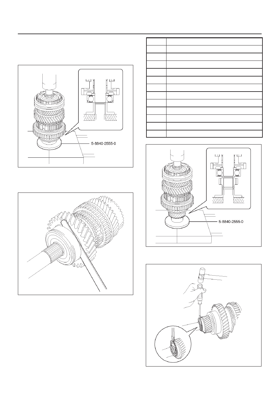
13. Install the mainshaft center bearing.
1. Using installer 5–8840–2555–0 (J–42799) and a
press, install the mainshaft center bearing.
NOTE: Center bearing snap ring groove toward rear.
226RW195
2. Using a thickness gauge, measure 1st gear thrust
clearance.
Standard: 0.10 – 0.45mm (0.004 – 0.018 in)
226RW118
14. Install the 5th gear.
1. Using installer 5–8840–2555–0 (J–42799) and a
press, install the 5th gear.
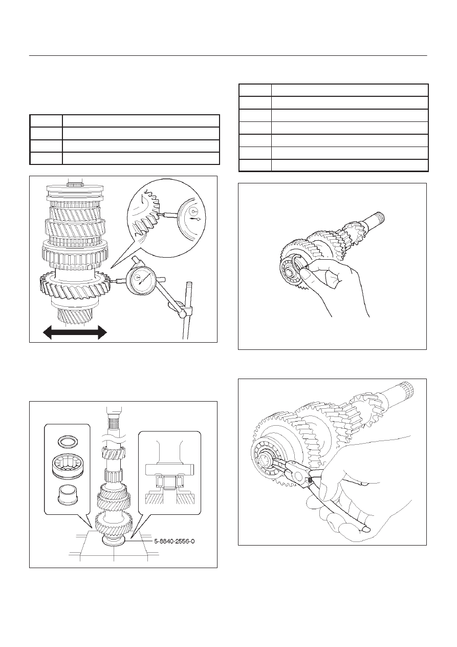
2. Select a snap ring that will allow minimum axial
play.
Mark
Thickness
C
2.75 – 2.80 mm (0.108 – 0.110 in)
D
2.80 – 2.85 mm (0.110 – 0.112 in)
E
2.85 – 2.90 mm (0.112 – 0.114 in)
F
2.90 – 2.95 mm (0.114 – 0.116 in)
G
2.95 – 3.00 mm (0.116 – 0.118 in)
H
3.00 – 3.05 mm (0.118 – 0.120 in)
J
3.05 – 3.10 mm (0.120 – 0.122 in)
K
3.10 – 3.15 mm (0.122 – 0.124 in)
L
3.15 – 3.20 mm (0.124 – 0.126 in)
M
3.20 – 3.25 mm (0.126 – 0.128 in)
N
3.25 – 3.30 mm (0.128 – 0.130 in)
P
3.30 – 3.35 mm (0.130 – 0.132 in)
226RW203
3. Using a screwdriver and hammer, install the new
snap ring.
226RW127
7B–50 MANUAL TRANSMISSION
15. Inspect each gear radial clearance.
1. Mount the mainshaft through the aluminum plate
in a vise.
2. Using a dial indicator, measure the radial
clearance of each gear.
Gear
Standard Clearanse
1st
0.020 – 0.073 mm (0.0008 – 0.0029 in)
2nd
0.015 – 0.068 mm (0.0006 – 0.0027 in)
3rd
0.015 – 0.068 mm (0.0006 – 0.0027 in)
226RW071
16. Install the counter gear shaft.
1. Check the new counter front bearing inner race
and the side race, as shown.
2. Using installer 5–8840–2556–0 (J–42800) and a
press, install the counter gear shaft front bearing.
226RW194
3. Select a snap ring that will allow minimum axial
play.
Mark
Thickness
A
2.00 – 2.05 mm (0.079 – 0.081 in)
B
2.05 – 2.10 mm (0.081 – 0.083 in)
C
2.10 – 2.15 mm (0.083 – 0.085 in)
D
2.15 – 2.20 mm (0.085 – 0.087 in)
E
2.20 – 2.25 mm (0.087 – 0.089 in)
F
2.25 – 2.30 mm (0.089 – 0.091 in)
226RW128
4. Using a snap ring expander, install the new snap
ring.
226RW129
MANUAL TRANSMISSION
7B–51
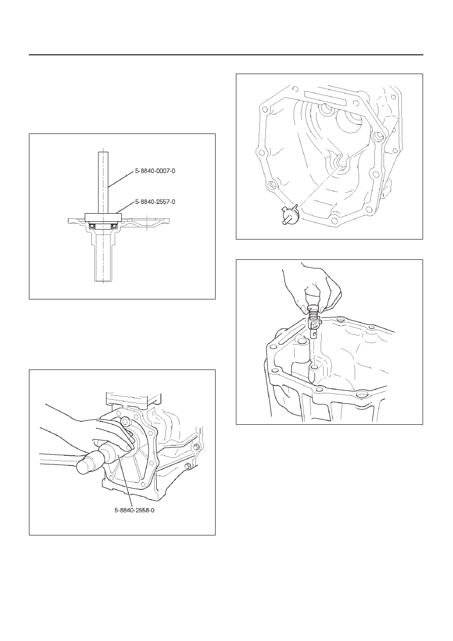
17. Install the front cover.
1. Using installer 5–8840–2557–0 (J–42801), grip
5–8840–0007–0 (J–8092) and a hammer, drive in
a new oil seal.
Drive in depth (from cover end): 11.7
±
0.5 mm
(0.46
±
0.02 in)
2. Apply grease to the seal lip.
220RW113
18. Install the transfer adapter.
1. Using installer 5–8840–2558–0 (J –42802), and a
hammer drive in a new oil seal.
Drive in depth (from transfer adapter):
10.95
±
0.5 mm (0.431
±
0.02 in)
2. Apply grease to the oil seal lip.
220RW114
3. Install the oil receiver pipe.
220RW011
4. Install the reverse restrict to the transfer adapter.
226RW059
7B–52 MANUAL TRANSMISSION
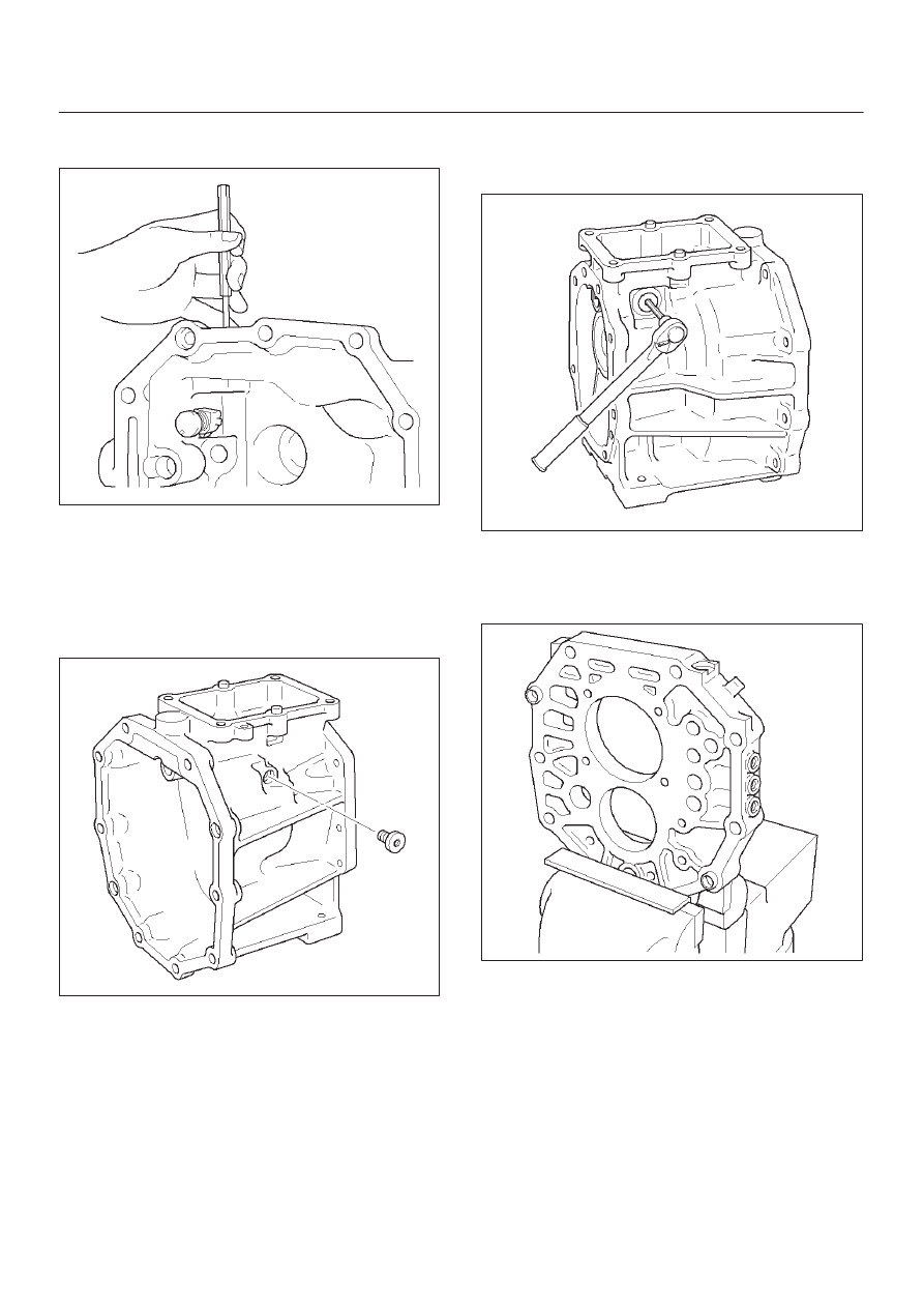
5. Using a pin punch and hammer, drive in the
slotted spring pin.
226RW058
6. Clean up the plug and plug hole.
7. Apply sealant to the plug threads. (THREE BOND
1344 or equivalent)
8. Using a torx socket wrench(T40), install and
torque the plug.
Torque: 19 N·m (1.9 kg·m/14 lb ft)
220RW013
9. Using hexagon wrench, install and torque the
plug.
Torque: 37 N·m (3.8 kg·m/27 lb ft)
220RW014
19. Install the reverse shift arm No.1 and reverse shift
arm No.2.
1. Mount the intermediate plate through the
aluminum plate in a vise.
226RW057
Нет комментариевНе стесняйтесь поделиться с нами вашим ценным мнением.
Текст