Opel Frontera UBS. Service manual — part 228
POWER ASSISTED BRAKE SYSTEM 5C – 57
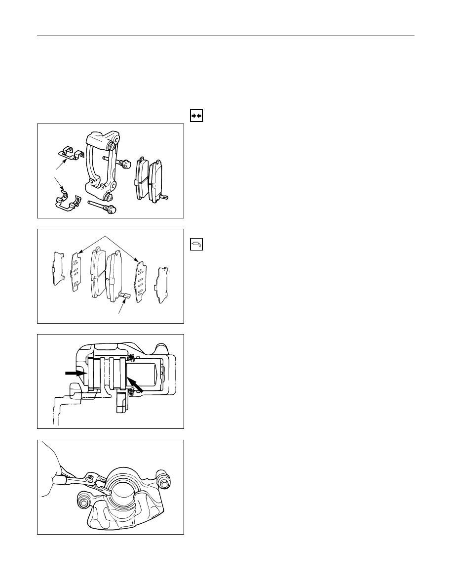
3. Caliper Assembly
•
Support the caliper assembly so that the brake
hose is not stretched or damaged.
4. Pad Assembly with Shim
5. Clip
INSTALLATION
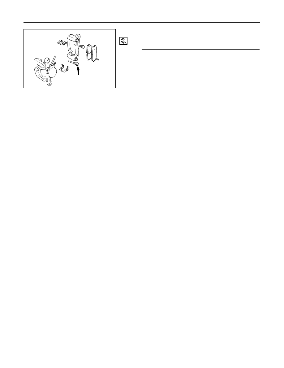
5. Clip
Clip
4. Pad Assembly with Shim
•
Apply special grease (approx. 0.2 g) to both
contacting surfaces of inner shims. Wipe off
extruded grease after installing.
Inner shim
Wear indicator
Apply
special
grease
3. Caliper Assembly
1) Use adjustable pliers to bottom the piston into the
caliper bore. Be careful not to damage the piston
dust boot.
2) Do not damage the flexible hose by twisting or
pulling it.
5C – 58 POWER ASSISTED BRAKE SYSTEM
2. Lock Bolt
Lock Bolt Torque
N·m (kg·m / lb·ft)
44 (4.5 / 32)
1. Wheel and Tire Assembly
1) Refer to Wheels and Tires in Suspension section.
2) Pump the brake pedal several times to make sure
that the pedal is firm. Check the brake fluid level
in the reservoir after pumping the brakes.
POWER ASSISTED BRAKE SYSTEM 5C – 59
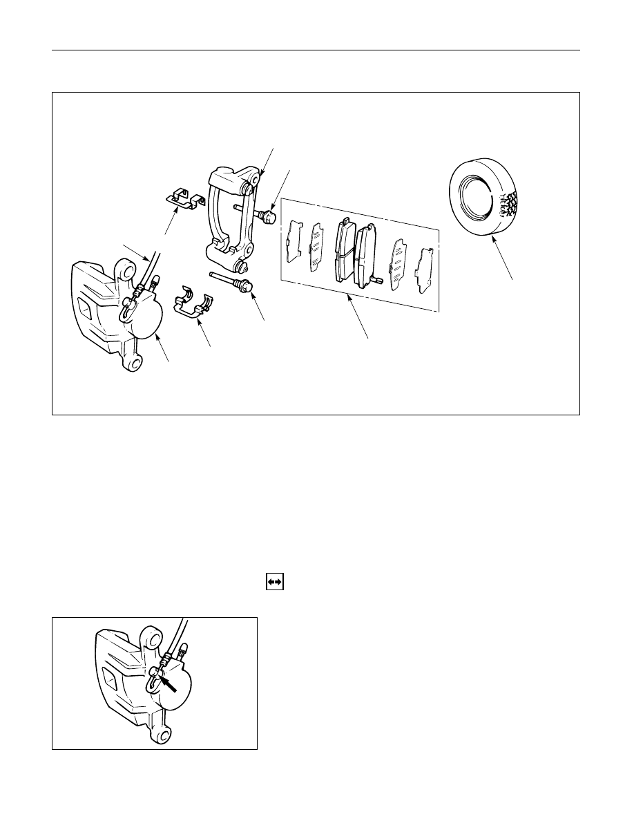
CALIPER REPLACEMENT
7
1
4
6
8
8
5
2
3
Removal Steps
1.
Wheel and tire assembly
2.
Brake flexible hose
3.
Lock bolt
4.
Guide bolt
5.
Caliper assembly
6.
Support bracket
7.
Pad assembly with shim
8.
Clip
Installation Steps
To install, follow the removal steps in the
reverse order.
REMOVAL
•
Raise the vehicle and support with suitable safety
stands.
1. Wheel and Tire Assembly
•
Refer to Wheels and Tires in Suspension section.
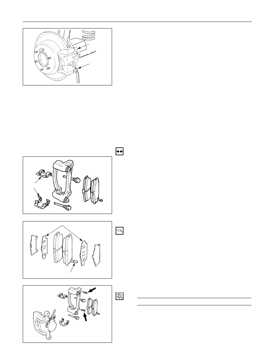
2. Brake Flexible Hose
1) Remove the bolt and gaskets, then disconnect the
flexible hose from the caliper.
2) After disconnecting the flexible hose, cap or tape
the openings to prevent entry of foreign material.
3) Since the brake fluid flows out from the
connecting coupler, place a drain pan under the
vehicle.
5C – 60 POWER ASSISTED BRAKE SYSTEM
3. Lock Bolt
4. Guide Bolt
4
3
5. Caliper Assembly
6
Support Bracket
•
Take care not to damage the flexible brake hose
when removing the support bracket.
7. Pad Assembly with Shim
•
Mark the lining locations if they are to be
reinstalled.
8. Clip
INSTALLATION
8. Clip
Clip
7. Pad Assembly with Shim
•
Apply special grease (approx. 0.2 g) to both
contacting surfaces of inner shims. Wipe off
extruded grease after installing.
Inner shim
Wear indicator
6. Support Bracket
Support Bracket Torque
N·m (kg·m / lb·ft)
104 (10.6 / 77)
5. Caliper Assembly
Нет комментариевНе стесняйтесь поделиться с нами вашим ценным мнением.
Текст