Opel Frontera UBS. Service manual — part 2446

6E–98
4JX1–TC ENGINE DRIVEABILITY AND EMISSIONS
DTC P0198 – OT Sensor High Voltage
(Cont'd)
Step
No
Yes
Value(s)
Action
8
1. Ignition “OFF.”
2. Disconnect the OT, and check the OT signal circuit
for an open.
3. If the OT sensor signal circuit is open, repair it as
necessary.
Was the OT signal circuit open?
—
Verify repair
Go to
Step 9
9
Check for a poor sensor ground or OT signal circuit
terminal connection at the ECM and replace
terminal(s) if necessary.
Did any of the terminals need to be replaced?
—
Verify repair
Go to
Step 11
10
Replace the ECT sensor.
Is the action complete?
—
Verify repair
—
11
Replace the ECM (Refer to the Data Programming in
Case of ECM change).
Is the action complete?
—
Verify repair
—

6E–99
4JX1–TC ENGINE DRIVEABILITY AND EMISSIONS
Diagnostic Trouble Code (DTC) P0201 (Flash DTC 51)
Injector # 1 Circuit Fault
060RW134
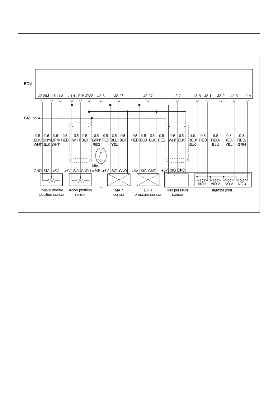
Circuit Description
The Engine Control Module ECM has four individual
injector driver circuits. Each controls an injector. When a
driver circuit is grounded by the ECM, the injector is
activated. The ECM monitors the current in each driver
circuit. The voltage on each driver is monitored to detect
a fault. If the voltage is not what the ECM expects to
monitor on the circuit, a DTC is set. This DTC is also set if
an injector driver is shorted to voltage or if there is an open
circuit.
Action Taken When the DTC Sets
D
The ECM will store conditions which were present
when the DTC was set as Freeze Frame and in the
Failure Records data.
Conditions for Clearing the MIL/DTC
D
DTC P0201 can be cleared by using the Tech 2 “Clear
Info” function or by disconnecting the ECM battery
feed.
Diagnostic Aids
An injector driver circuit that is open or shorted to voltage
will cause a DTC P0201 to set.
Test Description
The number(s) below refer to the step number(s) on the
Diagnostic Chart.
3. This step determines if DTC P0201 is the result of a
hard failure or an intermittent condition.
Injector Test
This test is conducted to make it sure that appropriate
electric signals are being sent to injectors Nos. 1–4.
Tech–2 must be used for this test.
Test Procedure:
1.
Connect Tech–2 to the vehicle DLC.
2.
Set Ignition Switch to the “ON” position.
3.
Select Control Test.
4.
Select Injector Test.
5.
Send instructions to each injector (Switch on),
making sure of injector working noise.
NOTE: If injector working noise (Clink) can hardly be
confirmed, remove the engine head cover noise
insulation.
Refer to Section 6A.
6.
In the injector whose working noise has been
confirmed, its electric circuit can be regarded as
normal.
As for the injector whose working noise has not
been confirmed, its electric circuit or the injector
proper is faulty.

6E–100
4JX1–TC ENGINE DRIVEABILITY AND EMISSIONS
DTC P0201 – Injector # 1 Circuit Fault
Step
Action
Value(s)
Yes
No
1
Was the “On-Board Diagnostic (OBD) System Check”
performed?
—
Go to
Step 2
Go to
OBD
System
Check
2
Will the engine start?
—
Go to
Step 3
Go to
Engine
Cranks But
Will Not Run
chart
3
1. Install the Tech 2. Clear the DTC.
2. Idle the engine for one minute.
Does DTC P0201 reset?
—
Go to
Step 5
Go to
Step 4
4
1. Review the Freeze Frame data with the ignition
“ON” and the engine “OFF” and note the
parameters.
2. Operate the vehicle within the Freeze Frame
conditions as noted.
Does P0201 reset?
—
Go to
Step 5
—
5
Check the Injector test.
Does the working noise confirm?
—
Go to
Step 6
Go to
Step 7
6
1. Install the Tech 2. Clear the DTC.
2. Idle the engine for one minute.
Dose DTC P0201 reset?
—
Verify repair
Go to
Step 7
7
Check for an open circuit between the injector
connector and the ECM.
Was there an open circuit?
—
Go to
Step 8
Go to
Step 9
8
Repair the open circuit.
Is the action complete?
—
Verify repair
—
9
Replace the ECM (Refer to the Data Programming in
Case of ECM change).
Is the action complete?
—
Verify repair
Go to
Step 10
10
Replace the Injector (Refer to the Injector Group Sign
Programming).
Is the action complete?
—
Verify repair
—
6E–101
4JX1–TC ENGINE DRIVEABILITY AND EMISSIONS
Diagnostic Trouble Code (DTC) P0202 (Flash DTC 52)
Injector # 2 Circuit Fault
060RW134
Circuit Description
The Engine Control Module ECM has four individual
injector driver circuits. Each controls an injector. When a
driver circuit is grounded by the ECM, the injector is
activated. The ECM monitors the current in each driver
circuit. The voltage on each driver is monitored to detect
a fault. If the voltage is not what the ECM expects to
monitor on the circuit, a DTC is set. This DTC is also set if
an injector driver is shorted to voltage or if there is an open
circuit.
Action Taken When the DTC Sets
D
The ECM will store conditions which were present
when the DTC was set as Freeze Frame and in the
Failure Records data.
Conditions for Clearing the MIL/DTC
D
DTC P0202 can be cleared by using the Tech 2 “Clear
Info” function or by disconnecting the ECM battery
feed.
Diagnostic Aids
An injector driver circuit that is open or shorted to voltage
will cause a DTC P0202 to set.
Test Description
The number(s) below refer to the step number(s) on the
Diagnostic Chart.
3. This step determines if DTC P0202 is the result of a
hard failure or an intermittent condition.
Injector Test
This test is conducted to make it sure that appropriate
electric signals are being sent to injectors Nos. 1–4.
Tech–2 must be used for this test.
Test Procedure:
1.
Connect Tech–2 to the vehicle DLC.
2.
Set Ignition Switch to the “ON” position.
3.
Select Control Test.
4.
Select Injector Test.
5.
Send instructions to each injector (Switch on),
making sure of injector working noise.
NOTE: If injector working noise (Clink) can hardly be
confirmed, remove the engine head cover noise
insulation.
Refer to Section 6A.
6.
In the injector whose working noise has been
confirmed, its electric circuit can be regarded as
normal.
As for the injector whose working noise has not
been confirmed, its electric circuit or the injector
proper is faulty.
Нет комментариевНе стесняйтесь поделиться с нами вашим ценным мнением.
Текст