Opel Frontera UBS. Service manual — part 377
SERVICE INFORMATION 00 – 31
Remove the radiator filler cap only when absolutely neces-
sary.
Always check the coolant level when the engine is cold.
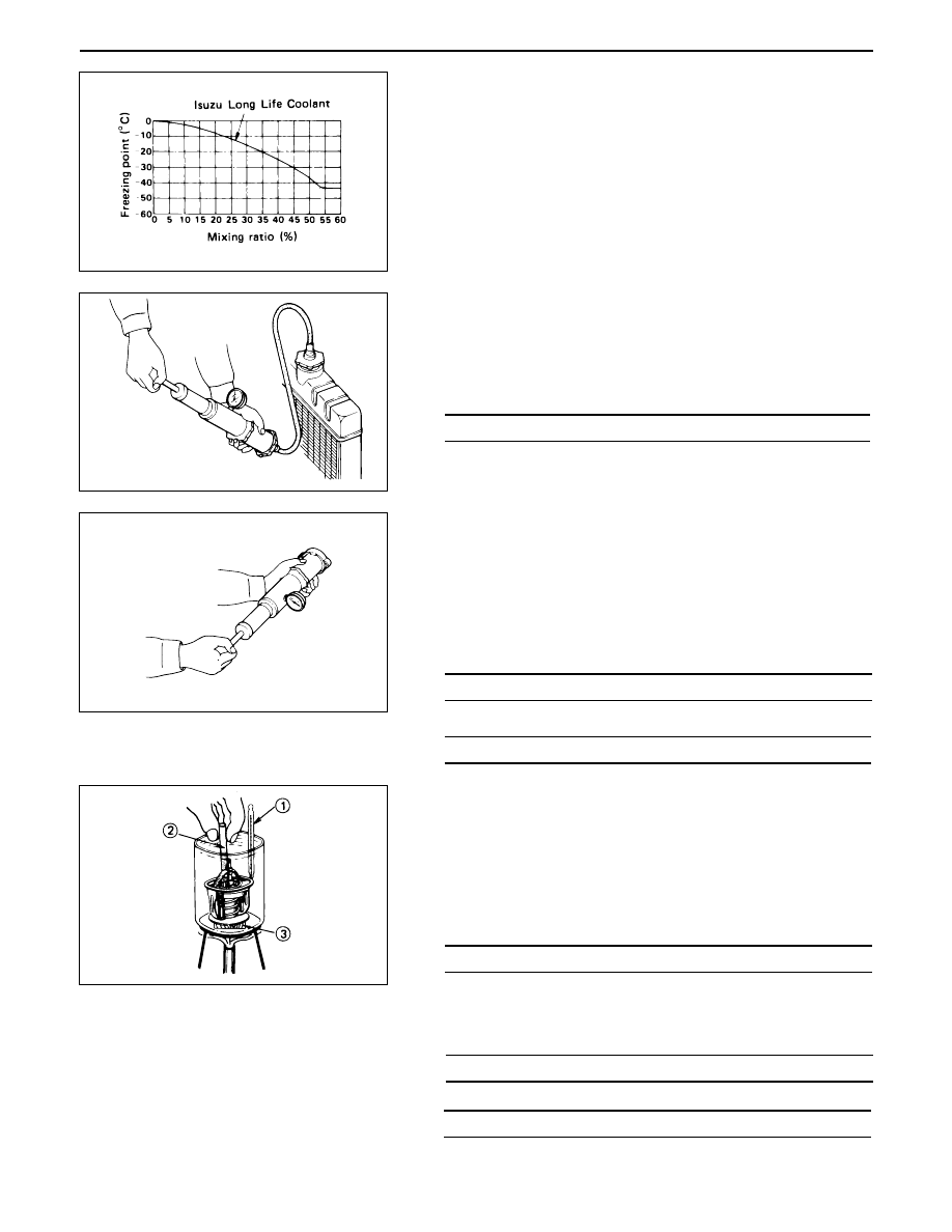
Always refer to the chart at the left to determine the correct
cooling water to antifreeze solution mixing ratio.
Cooling System Inspection
Install a radiator filler cap tester to the radiator. Apply
testing pressure to the cooling system to check for leakage.
The testing pressure must not exceed the specified pres-
sure.
Radiator Cap Inspection
The radiator filler cap is designed to maintain coolant pres-
sure in the cooling system at 1.05 kg/cm
2
(15 psi/103 kPa).
Check the radiator filler cap with a radiator filler cap tester.
The radiator filler cap must be replaced if it fails to hold the
specified pressure during the test procedure.
Radiator Filler Cap Pressure
Thermostat Operating Test
1.
Completely submerge the thermostat in water.
2.
Heat the water.
Stir the water constantly to avoid direct heat being
applied to the thermostat.
3.
Check the thermostat initial opening temperature.
82 (180)
°C(°F)
Thermostat Initial
Opening Temperature
4.
Check the thermostat full opening temperature.
1.0 – 3.9 (0.01 – 0.04/0.14 – 0.57)
Negative Valve (Reference)
Kpa (Kg/cm
2
/ Psi)
90 (194)
°C(°F)
Thermostat Full
Opening Temperature
10 (0.39)
mm(in)
Valve Lift at Fully Open Position
196 (2/28.45)
Testing Pressure
Kpa (Kg/cm
2
/ Psi)
93.3 – 122.7 (0.95 – 1.25/13.5 –17.8)
Pressure Valve
Kpa (Kg/cm
2
/ Psi)
00 – 32 SERVICE INFORMATION
Drive Belt Adjustment
Check the drive belt tension.
Depress the drive belt mid-portion with a 98N (10kg/22 lb)
force.
Cooling Fan Pulley Drive Belt
Fan belt tension is adjusted by moving the alternator.
Depress the drive belt mid-portion with a 98N (10Kg/22lb)
force.
1
Crankshaft damper pulley
2
Alternator pulley
3
Cooling fan pulley
Compressor Pulley Drive Belt
Move the idler pulley as required to adjust the compressor
drive belt tension.
If the vehicle is equipped with power steering, move the oil
pump as required.
Depress the drive belt mid-portion with a 98N (10Kg/22lb)
force.
1
Crankshaft damper pulley
2
Oil pump pulley or idler pulley
3
Compressor pulley
Power Steering Oil Pump Pulley Drive Belt
Move the oil pump as required to adjust the oil pump drive
belt tension.
On air conditioner equipped models, both drive belts pulley
must always be replaced as a set.
Depress the drive mid-portion with a 98N (10kg/22 lb) force.
1
Crankshaft damper pulley
2
Oil pump pulley
3
Compressor pulley or idler pulley
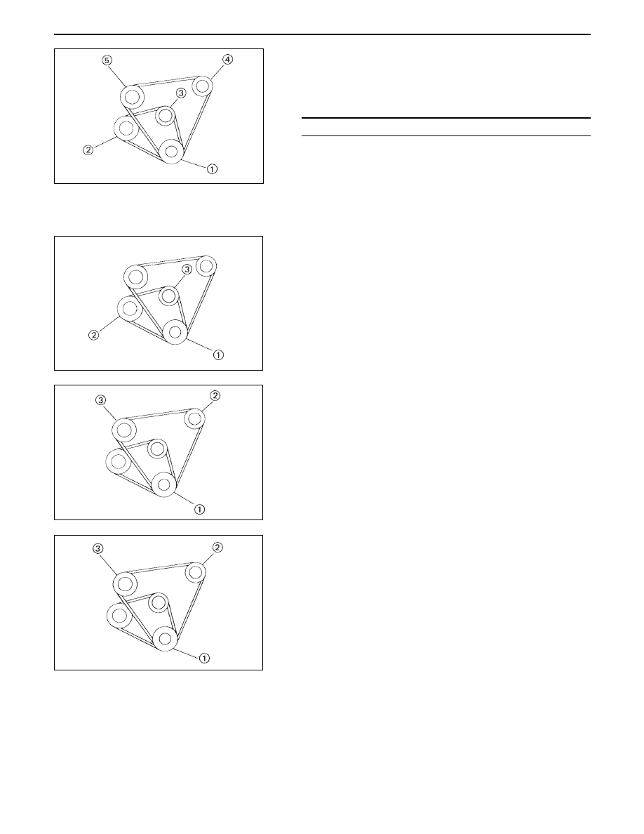
Check the drive belt for cracking and other damage.
1
Crankshaft damper pulley.
2
Alternator pulley
3
Cooling fan pulley
4
Oil pump pulley or idler pulley
5
Compressor pulley or idler pulley
10 (0.39)
mm(in)
Drive Belt Deflection
SERVICE INFORMATION 00 – 33
ENGINE CONTROL
Idling Speed Adjustment
1.
Set the vehicle parking brake and choke the drive wheels.
2.
Place the transmission in neutral.
3.
Start the engine and allow it to warm up.
4.
Disconnect the engine control cable from the control
lever.
5.
Set a tachometer to the engine.
6.
Check the engine idling speed.
If the engine idling speed is outside the specified range,
it must be adjusted.
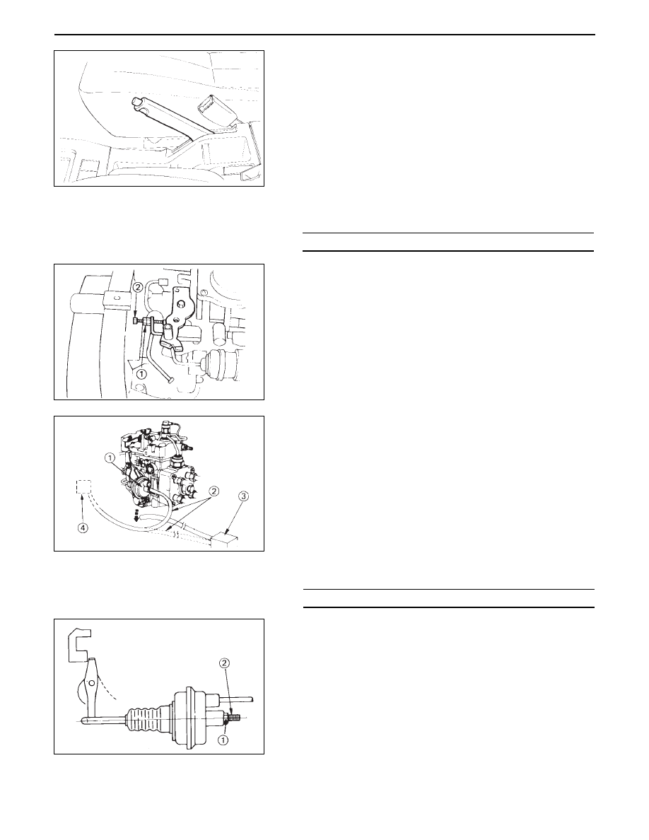
Fast Idling Speed Adjustment
1.
Loosen the fast idle actuator lock nut 1
.
2.
Adjust the fast idling speed by turning the adjusting
screw 2
.
3.
Tighten the lock nut 1
.
4.
Connect the vacuum hose to the fast idle actuator.
5.
Connect the other vacuum hose to the vacuum switch-
ing valve.
750 (4JG2-NA)/720 (4JG2-T)
rpm
Engine Idling Speed
Idling Speed Adjustment
1.
Loosen the idling set screw lock nut 1 on the injection
pump idling set bolt.
2.
Adjust the idling speed to the specified range by turning
the idling set bolt 2.
3.
Lock the idling set bolt with the idling set screw lock nut.
4.
Check that the idling control cable is tight (free of slack).
If required, remove the slack from the cable.
Fast Idling Speed Inspection
1.
Set tachometer to the engine.
2.
Disconnect the vacuum hose from the fast idle actuator
1 on the injection pump.
3.
Disconnect the other vacuum hose 2 from the vacuum
switching valve 3 and connect it to the fast idle actuator
1
.
The vacuum line will now be connected directly from
the vacuum pump 4 to the fast idle actuator.
4.
Check the engine fast idling speed.
If the engine idling speed is outside the specified range,
it must be adjusted.
850 – 950
rpm
Fast Idling Speed
00 – 34 SERVICE INFORMATION
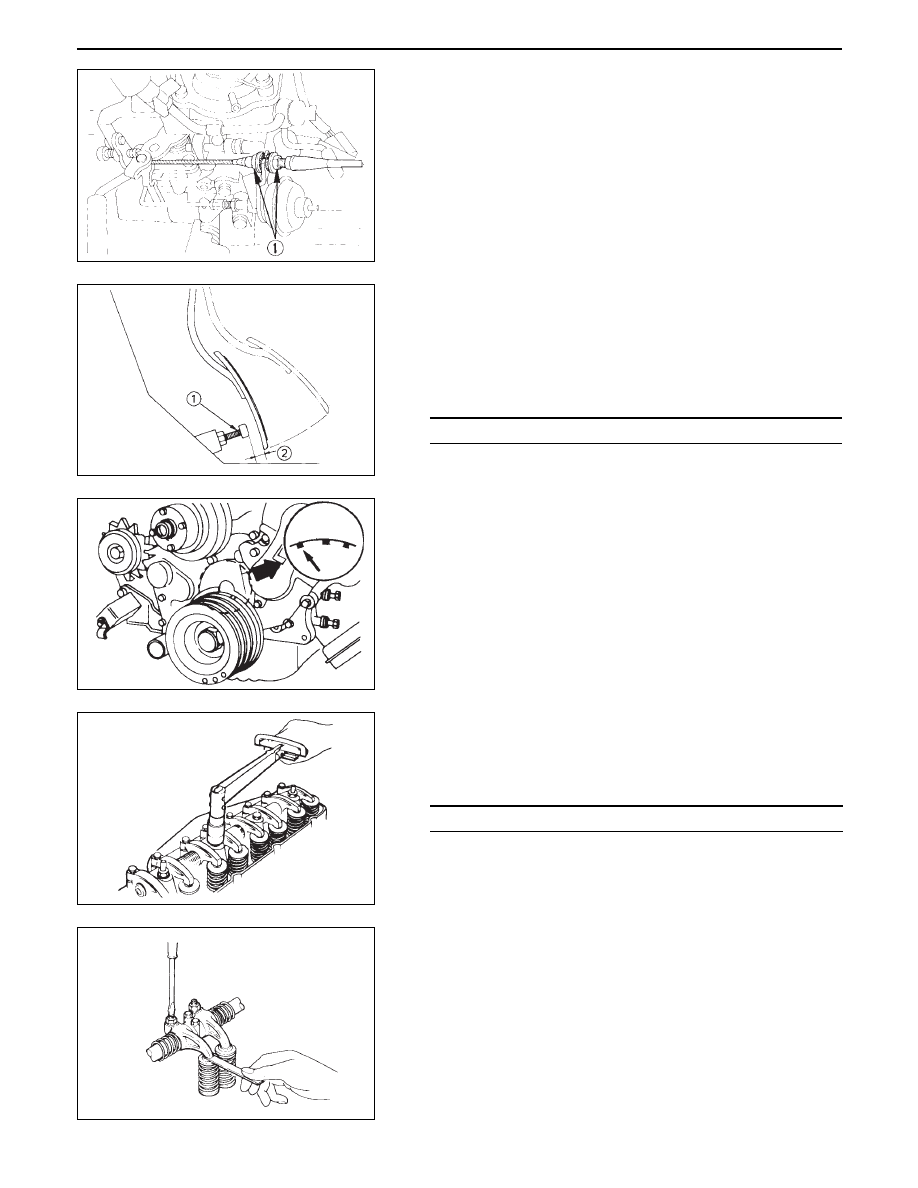
Accelerator Control
Accelerator Control Cable Adjustment
1.
Loosen the accelerator cable clamp bolt 1
.
2.
Check that the idling control knob on the instrument
panel is in the engine idling position.
3.
Hold the accelerator lever 2 in the fully closed position
and stretch the control cable 3
in the direction indi-
cated by the arrow to remove any slack.
Accelerator Pedal Adjustment
1.
Depress the accelerator pedal and hold it.
2.
Use the stopper bolt 1 to adjust the clearance between
the stopper bolt end and the accelerator pedal lower
face 2
.
VALVE CLEARANCE ADJUSTMENT
1.
Bring the piston in either the No. 1 cylinder or the No. 4
cylinder to TDC on the compression stroke by turning
the crankshaft until the crankshaft damper pulley TDC
line is aligned with the timing pointer.
2.
Check the rocker arm shaft bracket nuts for looseness.
Tighten any loose rocker arm shaft bracket nuts before
adjusting the valve clearance.
3.
Check for play in the No. 1 intake and exhaust valve push
rods.
If the No. 1 cylinder intake and exhaust valve push rods
have play, the No. 1 piston is at TDC on the compression
stroke.
If the No.1 cylinder intake and exhaust valve push rods
are depressed, the No. 4 piston is at TDC on the com-
pression stroke.
54 (5.5/40)
N·m(Kg·m/lb·ft)
Rocker Arm Shaft
Bracket Nut Torque
2 – 5 (0.08 – 0.20)
mm(in)
Accelerator and
Stopper Bolt Clearance
Нет комментариевНе стесняйтесь поделиться с нами вашим ценным мнением.
Текст