Opel Frontera UBS. Service manual — part 1370

6E–74
4JX1–TC ENGINE DRIVEABILITY AND EMISSIONS
DTC P0122 –AP Sensor Low Voltage
(Cont'd)
Step
No
Yes
Value(s)
Action
12
Replace the AP sensor.
Is the action complete?
—
Verify repair
—
13
Replace the ECM (Refer to the Data Programming in
Case of ECM change).
Is the action complete?
—
Verify repair
—
6E–75
4JX1–TC ENGINE DRIVEABILITY AND EMISSIONS
Diagnostic Trouble Code (DTC) P0123 (Flash DTC 21)
AP Sensor High Voltage
060RW134
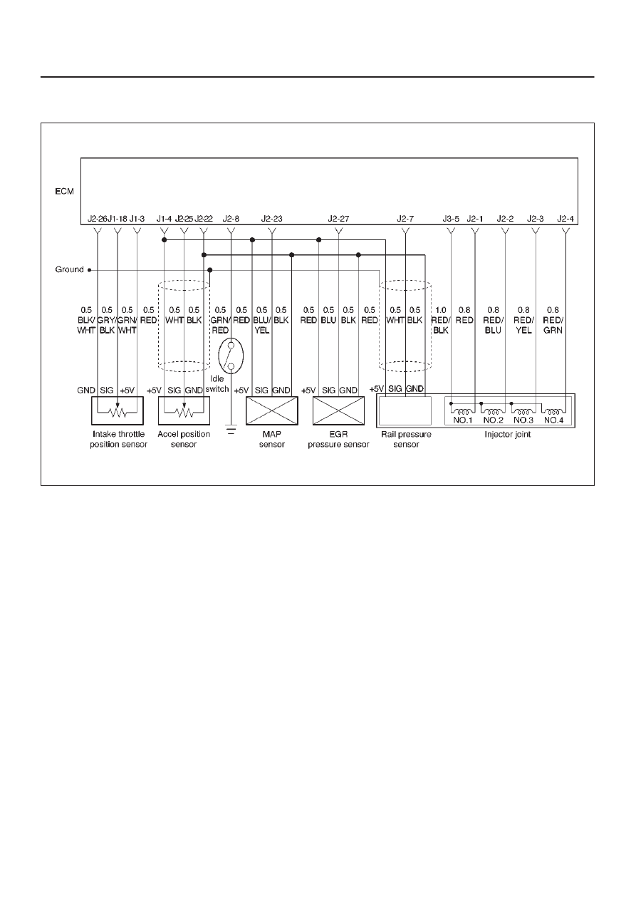
Circuit Description
The accelerator position (AP) sensor circuit provides a
voltage signal that changes relative to throttle blade
angle.
The TP signal is one of the most important inputs used by
the Engine Control Module ECM for fuel volume control
and many of the ECM-controlled outputs.
Action Taken When the DTC Sets
D
The ECM will store conditions which were present
when the DTC was set as Freeze Frame and in the
Failure Records data.
Conditions for Clearing the MIL/DTC
D
DTC P0123 can be cleared by using the Tech 2 “Clear
Info” function or by disconnecting the ECM battery
feed.
Diagnostic Aids
Check for the following conditions:
D
Poor connection at ECM – Inspect harness connectors
for backed-out terminals, improper mating, broken
locks, improperly formed or damaged terminals, and
poor terminal-to-wire connection.
D
Damaged harness – Inspect the wiring harness for
damage. If the harness appears to be OK, observe the
AP sensor display on the Tech 2 while moving
connectors and wiring harnesses related to the TP
sensor. A change in the display will indicate the
location of the fault.
D
Faulty AP sensor – With the ignition key “ON,” engine
“OFF,” observe the AP sensor display on the Tech 2
while slowly depressing the accelerator to wide open
throttle. If a voltage over 4.88 volts is seen at any point
in normal accelerator travel, replace the AP sensor.
If DTC P0123 cannot be duplicated, the information
included in the Failure Records data can be useful in
determining vehicle mileage since the DTC was last set.
Test Description
Number (s) below refer to the step number(s) on the
Diagnostic Chart.
8. Components that share the AP sensor 5 volt reference
“A” circuit include the following device:

6E–76
4JX1–TC ENGINE DRIVEABILITY AND EMISSIONS
DTC P0123 – AP Sensor High Voltage
Step
Action
Value(s)
Yes
No
1
Was the “On-Board Diagnostic (OBD) System Check”
performed?
—
Go to
Step 2
Go to
OBD
System
Check
2
Check the AP sensor signal circuit.
Was the AP sensor signal circuit open or darmage?
—
Replace the
APS circuit
Go to
Step 3
3
1. Ignition “ON,” engine “OFF.”
2. With the throttle closed, observe the “AP Sensor”
display on the Tech 2.
Is the “AP Sensor” above the specified value?
4.5 V
Go to
Step 5
Go to
Step 4
4
1. Ignition “ON,” engine “OFF.”
2. Review and record Tech 2 Failure Records data.
3. Operate the vehicle within Failure Records
conditions as noted.
4. Using a Tech 2, monitor “DTC” info for DTC P0123.
Does the Tech 2 indicate DTC P0123 failed.
—
Go to
Step 5
Refer to
Diagnostic
Aids
5
1. Disconnect the AP sensor electrical connector.
2. Observe the “AP Sensor” display on the Tech 2.
Is the “AP Sensor” near the specified value?
0 V
Go to
Step 6
Go to
Step 7
6
Probe the sensor ground circuit at the AP sensor
harness connector with a test light connected to B+.
Is the test light “ON?”
—
Go to
Step 8
Go to
Step 11
7
1. Ignition “OFF,” disconnect the ECM.
2. Ignition “ON,” engine “OFF.”
3. Check for a short to voltage on the AP sensor signal
circuit.
4. If the AP sensor signal circuit is shorted, repair it as
necessary.
Was the AP sensor signal circuit shorted?
—
Verify repair
Go to
Step 13
8
1. Ignition “ON.”
2. Monitor the “AP Sensor” Tech 2 display while
disconnecting each of the components that share
the 5 volt reference “J2” circuit (one at a time).
3. If the “AP Sensor” Tech 2 display changes, replace
the component that caused the display to change
when disconnected.
Does disconnecting any of these components cause
the “AP Sensor” display to change?
—
Verify repair
Go to
Step 9
9
1. Ignition “OFF,” disconnect the ECM.
2. Ignition “ON,” engine “OFF.”
3. Check for a short to B+ on the 5 volt reference “A”
circuit.
4. If the 5 volt reference “J2” circuit is shorted, repair it
as necessary.
Was the 5 volt reference “J2” circuit shorted?
—
Verify repair
Go to
Step 10
10
Check for poor electrical connections at the AP sensor
and replace terminals if necessary.
Did any terminals require replacement?
—
Verify repair
Go to
Step 12

6E–77
4JX1–TC ENGINE DRIVEABILITY AND EMISSIONS
DTC P0123 – AP Sensor High Voltage
(Cont'd)
Step
No
Yes
Value(s)
Action
11
1. Ignition “OFF.”
2. Disconnect the ECM, and check for an open sensor
ground circuit to the AP sensor.
3. If a problem is found, repair it as necessary.
Was the sensor ground circuit to the AP sensor open?
—
Verify repair
Go to
Step 13
12
Replace the AP sensor.
Is the action complete?
—
Verify repair
—
13
Replace the ECM (Refer to the Data Programming in
Case of ECM change).
Is the action complete?
—
Verify repair
—
Нет комментариевНе стесняйтесь поделиться с нами вашим ценным мнением.
Текст