Opel Frontera UBS. Service manual — part 2030
4D2–43
TRANSFER CASE (TOD)
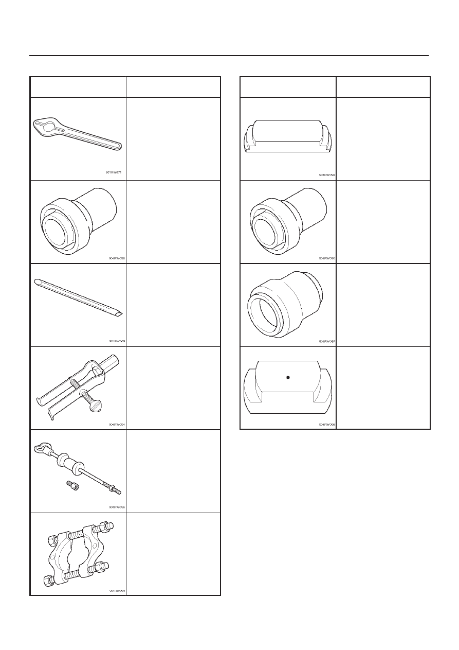
Special Tools
ILLUSTRATION
TOOL NO.
TOOL NAME
5–8840–0133–0
(J–8614–11)
Flange Holder
5–8840–2412–0
(J–42804)
Rear Oil Seal Installer
5–8840–2293–0
(J–39209)
Punch
5–8840–2409–0
(J–42805)
Bearing Remover
5–8840–0084–0
(J–2619–01)
Slide Hammer
5–8840–0015–0
(J–22912–01)
Bearing Remover
ILLUSTRATION
TOOL NO.
TOOL NAME
5–8840–2413–0
(J–42806)
Ring Gear Replacer
5–8840–2410–0
(J–42807)
Front Out Oil Seal
Installer
5–8840–2411–0
(J–42808)
Input Shaft Oil Seal
Installer
5–8840–2416–0
(J–42809)
Ring Gear Installer
5A–1
BRAKE CONTROL SYSTEM
BRAKES
CONTENTS
Brake Control System
5A
. . . . . . . . . . . . . . . . . . . .
Anti–lock Brake System
5B
. . . . . . . . . . . . . . . . . .
Power–Assisted Brake System
5C
. . . . . . . . . . . .
Parking Brakes
5D
. . . . . . . . . . . . . . . . . . . . . . . . .
BRAKE CONTROL SYSTEM
CONTENTS
Service Precaution
5A–2
. . . . . . . . . . . . . . . . . . . . . .
General Description
5A–3
. . . . . . . . . . . . . . . . . . . . .
System Components
5A–3
. . . . . . . . . . . . . . . . . . .
Electronic Hydraulic Control Unit (EHCU)
5A–3
.
ABS Warning Light
5A–4
. . . . . . . . . . . . . . . . . . . .
Wheel Speed Sensor
5A–4
. . . . . . . . . . . . . . . . . .
G-Sensor
5A–4
. . . . . . . . . . . . . . . . . . . . . . . . . . . . .
Normal and Anti-lock Braking
5A–4
. . . . . . . . . . .
Brake Pedal Travel
5A–4
. . . . . . . . . . . . . . . . . . . .
Acronyms and Abbreviations
5A–4
. . . . . . . . . . . .
General Diagnosis
5A–5
. . . . . . . . . . . . . . . . . . . . . . .
General Information
5A–5
. . . . . . . . . . . . . . . . . . . .
ABS Service Precautions
5A–5
. . . . . . . . . . . . . . .
Computer System Service Precautions
5A–5
. . .
General Service Precautions
5A–5
. . . . . . . . . . . .
Note on Intermittents
5A–5
. . . . . . . . . . . . . . . . . . .
Test Driving ABS Complaint Vehicles
5A–6
. . . . .
“ABS” Warning Light
5A–6
. . . . . . . . . . . . . . . . . . .
Normal Operation
5A–6
. . . . . . . . . . . . . . . . . . . . .
Basic Diagnostic Flow Chart
5A–6
. . . . . . . . . . . .
Basic Inspection Procedure
5A–7
. . . . . . . . . . . . .
Tech 2 Scan Tool
5A–8
. . . . . . . . . . . . . . . . . . . . . .
Getting Started
5A–9
. . . . . . . . . . . . . . . . . . . . . . . .
Operating Procedure
5A–10
. . . . . . . . . . . . . . . . . . .
Data List
5A–11
. . . . . . . . . . . . . . . . . . . . . . . . . . . . .
EHCU Connector Pin-out Checks
5A–12
. . . . . . . .
Circuit Diagram (LHD model / 6VD1 and
4JG2)
5A–13
. . . . . . . . . . . . . . . . . . . . . . . . . . . . . . .
Circuit Diagram (LHD model / 4JG2)
5A–14
. . . . .
Circuit Diagram (LHD model / 4JG2)
5A–15
. . . . .
Circuit Diagram (LHD model / 6VD1)
5A–16
. . . . .
Circuit Diagram (LHD model / 6VD1)
5A–17
. . . . .
Connector List (LHD model)
5A–18
. . . . . . . . . . . .
Part Location (LHD model)
5A–20
. . . . . . . . . . . . . .
Circuit Diagram (RHD model / 6VD1 and
4JG2)
5A–21
. . . . . . . . . . . . . . . . . . . . . . . . . . . . . . .
Circuit Diagram (RHD model / 4JG2)
5A–22
. . . . .
Circuit Diagram (RHD model / 4JG2)
5A–23
. . . . .
Circuit Diagram (RHD model / 6VD1)
5A–24
. . . . .
Circuit Diagram (RHD model / 6VD1)
5A–25
. . . . .
Circuit Diagram (RHD model / 6VE1 and
4JX1)
5A–26
. . . . . . . . . . . . . . . . . . . . . . . . . . . . . . . .
Circuit Diagram (RHD model / 4JX1)
5A–27
. . . . .
Circuit Diagram (RHD model / 4JX1)
5A–28
. . . . .
Circuit Diagram (RHD model / 6VE1)
5A–29
. . . . .
Circuit Diagram (RHD model / 6VE1)
5A–30
. . . . .
Connector List (RHD model)
5A–31
. . . . . . . . . . . .
Part Location (RHD model)
5A–34
. . . . . . . . . . . . .
Symptom Diagnosis
5A–35
. . . . . . . . . . . . . . . . . . . . .
Chart A–1 ABS Works Frequently But
Vehicle Does Not Decelerate
5A–35
. . . . . . . . . . .
Chart TA-1 ABS Works Frequently But
Vehicle Does Not Decelerate (Use
TECH 2)
5A–36
. . . . . . . . . . . . . . . . . . . . . . . . . . . . .
Chart A-2 Uneven Braking Occurs While
ABS Works
5A–36
. . . . . . . . . . . . . . . . . . . . . . . . . . .
Chart A-3, TA-3 The Wheels Are Locked
5A–36
.
Chart A-4 Brake Pedal Feed Is Abnormal
5A–37
.
Chart A-5, TA-5 Braking Sound (From
EHCU) Is Heard While Not Braking
5A–38
. . . . . .
Diagnostic Trouble Codes
5A–39
. . . . . . . . . . . . . . . .
Diagnosis By “ABS” Warning Light
Illumination Pattern
5A–40
. . . . . . . . . . . . . . . . . . . . .
Diagnostic Trouble Codes (DTCs)
5A–40
. . . . . . .
Chart B-1 With the key in the ON position
(Before starting the engine). Warning light
(W/L) is not activated.
5A–43
. . . . . . . . . . . . . . . . .
Chart B-2 EHCU Abnormality (DTC 14)
5A–43
. . .
Chart B-3 Power Voltage Drop (DTC 15)
5A–44
. .
Chart B-4 CLASS-2 Communication Line
Abnormality (DTC 16)
5A–44
. . . . . . . . . . . . . . . . .
Chart B-5 G-Sensor Circuit (DTC 21)
5A–45
. . . . .
Chart B-6 Abnormal Transmission Input
(DTC 23)
5A–46
. . . . . . . . . . . . . . . . . . . . . . . . . . . .
Chart B-7 Transfer Monitor (DTC 24)
5A–47
. . . . .
Chart B-8 EHCU Pump Motor And Motor
Relay Circuit (DTC 32)
5A–47
. . . . . . . . . . . . . . . . .
Chart B-9 EHCU Pump Valve And Valve
Relay Circuit (DTC 35)
5A–47
. . . . . . . . . . . . . . . . .
Chart B-10 FL Isolation Solenoid Valve
Abnormality (DTC 41)
5A–48
. . . . . . . . . . . . . . . . .
Chart B-11 FL Dump Solenoid Valve
Abnormality (DTC 42)
5A–48
. . . . . . . . . . . . . . . . .
Chart B-12 FR Isolation Solenoid Valve
Abnormality (DTC 43)
5A–48
. . . . . . . . . . . . . . . . .
Chart B-13 FR Dump Solenoid Valve
Abnormality (DTC 44)
5A–49
. . . . . . . . . . . . . . . . .
Chart B-14 Rear Isolation Solenoid Valve
Abnormality (DTC 45)
5A–49
. . . . . . . . . . . . . . . . .
Chart B-15 Rear Dump Solenoid Valve
Abnormality (DTC 46)
5A–49
. . . . . . . . . . . . . . . . .
5A–2
BRAKE CONTROL SYSTEM
Chart B-16 FL Speed Sensor Disconnection
(DTC 51)
5A–50
. . . . . . . . . . . . . . . . . . . . . . . . . . . .
Chart B-17 FR Speed Sensor Disconnection
(DTC 52)
5A–50
. . . . . . . . . . . . . . . . . . . . . . . . . . . .
Chart B-18 RL Speed Sensor Disconnection
(DTC 53)
5A–51
. . . . . . . . . . . . . . . . . . . . . . . . . . . .
Chart B-19 RR Speed Sensor Disconnection
(DTC 54)
5A–51
. . . . . . . . . . . . . . . . . . . . . . . . . . . .
Chart B-20 FL Speed Sensor Short Circuit
(DTC 61)
5A–52
. . . . . . . . . . . . . . . . . . . . . . . . . . . .
Chart B-21 FR Speed Sensor Short Circuit
(DTC 62)
5A–53
. . . . . . . . . . . . . . . . . . . . . . . . . . . .
Chart B-22 RL Speed Sensor Short Circuit
(DTC 63)
5A–54
. . . . . . . . . . . . . . . . . . . . . . . . . . . .
Chart B-23 RR Speed Sensor Short Circuit
(DTC 64)
5A–55
. . . . . . . . . . . . . . . . . . . . . . . . . . . .
Chart B-24 Sensor Signal Input Abnormality
(DTC 65)
5A–56
. . . . . . . . . . . . . . . . . . . . . . . . . . . .
Sensor Signal Abnormality Criteria using
TECH 2
5A–56
. . . . . . . . . . . . . . . . . . . . . . . . . . . . . .
Unit Inspection Procedure
5A–57
. . . . . . . . . . . . . . . .
Chart C-1-1 FL Sensor Output Inspection
Procedure
5A–57
. . . . . . . . . . . . . . . . . . . . . . . . . . .
Chart C-1-2 FR Sensor Output Inspection
Procedure
5A–58
. . . . . . . . . . . . . . . . . . . . . . . . . . .
Chart C-1-3 RL Sensor Output Inspection
Procedure
5A–58
. . . . . . . . . . . . . . . . . . . . . . . . . . .
Chart C-1-4 RR Sensor Output Inspection
Procedure
5A–59
. . . . . . . . . . . . . . . . . . . . . . . . . . .
Chart TC-1 Sensor Output Inspection
Procedure (Use TECH 2)
5A–59
. . . . . . . . . . . . . .
Chart C-2 Transmission Input Inspection
Procedure
5A–60
. . . . . . . . . . . . . . . . . . . . . . . . . . .
Chart TC-2 Transmission Input Inspection
Procedure (Use TECH 2)
5A–61
. . . . . . . . . . . . . .
Special Tools
5A–62
. . . . . . . . . . . . . . . . . . . . . . . . . . .
Service Precaution
WARNING: IF SO EQUIPPED WITH A
SUPPLEMENTAL RESTRAINT SYSTEM (SRS),
REFER TO THE SRS COMPONENT AND WIRING
LOCATION VIEW IN ORDER TO DETERMINE
WHETHER YOU ARE PERFORMING SERVICE ON OR
NEAR THE SRS COMPONENTS OR THE SRS
WIRING. WHEN YOU ARE PERFORMING SERVICE
ON OR NEAR THE SRS COMPONENTS OR THE SRS
WIRING, REFER TO THE SRS SERVICE
INFORMATION. FAILURE TO FOLLOW WARNINGS
COULD RESULT IN POSSIBLE AIR BAG
DEPLOYMENT, PERSONAL INJURY, OR
OTHERWISE UNNEEDED SRS SYSTEM REPAIRS.
CAUTION: Always use the correct fastener in the
proper location. When you replace a fastener, use
ONLY the exact part number for that application.
ISUZU will call out those fasteners that require a
replacement after removal. ISUZU will also call out
the fasteners that require thread lockers or thread
sealant. UNLESS OTHERWISE SPECIFIED, do not
use supplemental coatings (Paints, greases, or other
corrosion inhibitors) on threaded fasteners or
fastener joint interfaces. Generally, such coatings
adversely affect the fastener torque and the joint
clamping force, and may damage the fastener. When
you install fasteners, use the correct tightening
sequence and specifications. Following these
instructions can help you avoid damage to parts and
systems.
5A–3
BRAKE CONTROL SYSTEM
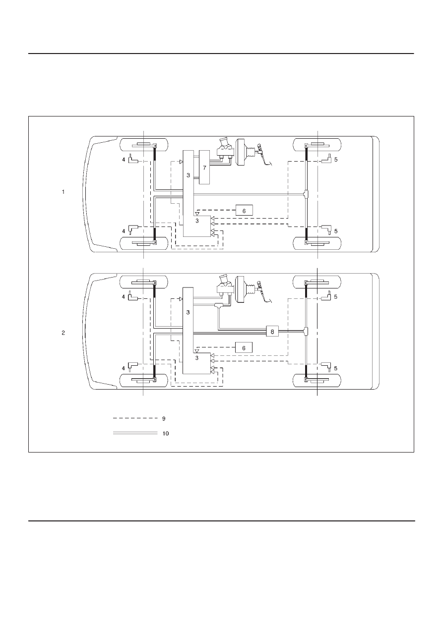
General Description
The Anti-lock Brake System (ABS) works on all four
wheels. A combination of wheel speed sensor and
Electronic Hydraulic Control Unit (EHCU) can determine
when a wheel is about to stop turning and adjust brake
pressure to maintain best braking.
This system helps the driver maintain greater control of
the vehicle under heavy braking conditions.
C05RW027
Legend
(1) With P&B Valve Model
(2) With LSPV Model
(3) Electronic Hydraulic Control Unit (EHCU)
(4) Front Wheel Speed Sensor
(5) Rear Wheel Speed Sensor
(6) G-Sensor
(7) Proportioning and Bypass (P&B) Valve
(8) Load Sensing Proportioning Valve (LSPV)
(9) Electronic Line
(10) Hydraulic Line
System Components
Electronic Hydraulic Control Unit (EHCU), four Wheel
Speed Sensors, Warning Light, and G-sensor.
Electronic Hydraulic Control Unit (EHCU)
The EHCU consists of ABS control circuits, fault detector,
and a fail-safe. It drives the hydraulic unit according to the
signal from each sensor, cancelling ABS to return to
Нет комментариевНе стесняйтесь поделиться с нами вашим ценным мнением.
Текст