Opel Frontera UBS. Service manual — part 29

AIR CONDITIONING 1B – 1
CAUTION
When fasteners are removed, always
reinstall them at the same location from
which they were removed. If a fastener
needs to be replaced, use the correct part
number fastener for that application. If the
correct part number fastener is not available,
a fastener of equal size and strength (or
stronger) may be used.
Fasteners that are not reused, and those
requiring thread locking compound, will be
called out. The correct torque values must
be used when installing fasteners that
require it. If the above conditions are not
followed, parts or system damage could
result.
SECTION 1B
AIR CONDITIONING
CONTENTS
PAGE
General Description . . . . . . . . . . . . . . . . . . . . . . . . . . . . . . . . . . . . . . . . . . . . . . . . . . . . . 1B–
3
Air Conditioning Refrigerant Cycle Construction . . . . . . . . . . . . . . . . . . . . . . . . . . . 1B–
3
Compressor . . . . . . . . . . . . . . . . . . . . . . . . . . . . . . . . . . . . . . . . . . . . . . . . . . . . . . . . . 1B–
4
Magnetic Clutch . . . . . . . . . . . . . . . . . . . . . . . . . . . . . . . . . . . . . . . . . . . . . . . . . . . . . . 1B–
5
Receiver/Drier . . . . . . . . . . . . . . . . . . . . . . . . . . . . . . . . . . . . . . . . . . . . . . . . . . . . . . . 1B–
5
Dual Pressure Switch . . . . . . . . . . . . . . . . . . . . . . . . . . . . . . . . . . . . . . . . . . . . . . . . . 1B–
6
Triple Pressure Switch . . . . . . . . . . . . . . . . . . . . . . . . . . . . . . . . . . . . . . . . . . . . . . . . 1B–
6
Expansion Valve. . . . . . . . . . . . . . . . . . . . . . . . . . . . . . . . . . . . . . . . . . . . . . . . . . . . . . 1B–
6
Evaporator . . . . . . . . . . . . . . . . . . . . . . . . . . . . . . . . . . . . . . . . . . . . . . . . . . . . . . . . . . 1B–
7
Electronic Thermostat . . . . . . . . . . . . . . . . . . . . . . . . . . . . . . . . . . . . . . . . . . . . . . . . . 1B–
7
Refrigerant Line . . . . . . . . . . . . . . . . . . . . . . . . . . . . . . . . . . . . . . . . . . . . . . . . . . . . . . 1B–
7
Service Charge Valve. . . . . . . . . . . . . . . . . . . . . . . . . . . . . . . . . . . . . . . . . . . . . . . . . . 1B–
7
Air Conditioning Parts . . . . . . . . . . . . . . . . . . . . . . . . . . . . . . . . . . . . . . . . . . . . . . . . . 1B–
8
On-Vehicle Service. . . . . . . . . . . . . . . . . . . . . . . . . . . . . . . . . . . . . . . . . . . . . . . . . . . . . . 1B– 13
Precautions For Replacement or Repair of Air Conditioning Parts. . . . . . . . . . . . . 1B– 13
Compressor Assembly and Associated Parts . . . . . . . . . . . . . . . . . . . . . . . . . . . . . . 1B– 23
Condenser Assembly (LHD V6 without Condenser Fan) . . . . . . . . . . . . . . . . . . . . . 1B– 33
Condenser Fan Motor . . . . . . . . . . . . . . . . . . . . . . . . . . . . . . . . . . . . . . . . . . . . . . . . . 1B– 35
Receiver/Drier . . . . . . . . . . . . . . . . . . . . . . . . . . . . . . . . . . . . . . . . . . . . . . . . . . . . . . . 1B– 37
Pressure Switch . . . . . . . . . . . . . . . . . . . . . . . . . . . . . . . . . . . . . . . . . . . . . . . . . . . . . . 1B– 39
Evaporator Assembly . . . . . . . . . . . . . . . . . . . . . . . . . . . . . . . . . . . . . . . . . . . . . . . . . 1B– 42
Evaporator Core and/or Expansion Valve . . . . . . . . . . . . . . . . . . . . . . . . . . . . . . . . . 1B– 44
Electronic Thermostat . . . . . . . . . . . . . . . . . . . . . . . . . . . . . . . . . . . . . . . . . . . . . . . . . 1B– 47
A/C Switch and Illumination Bulb . . . . . . . . . . . . . . . . . . . . . . . . . . . . . . . . . . . . . . . 1B– 48
Refrigerant Line . . . . . . . . . . . . . . . . . . . . . . . . . . . . . . . . . . . . . . . . . . . . . . . . . . . . . . 1B– 49
Rear Cooler Parts . . . . . . . . . . . . . . . . . . . . . . . . . . . . . . . . . . . . . . . . . . . . . . . . . . . . . 1B– 51
1B – 2 AIR CONDITIONING
Full Automatic Air Conditioning System. . . . . . . . . . . . . . . . . . . . . . . . . . . . . . . . . . . . 1B– 60
General Description . . . . . . . . . . . . . . . . . . . . . . . . . . . . . . . . . . . . . . . . . . . . . . . . . . . . . 1B– 60
Full Automatic Air Conditioner Part Configuration . . . . . . . . . . . . . . . . . . . . . . . . . 1B– 60
Circuit Diagram . . . . . . . . . . . . . . . . . . . . . . . . . . . . . . . . . . . . . . . . . . . . . . . . . . . . . . 1B– 62
Function and Features. . . . . . . . . . . . . . . . . . . . . . . . . . . . . . . . . . . . . . . . . . . . . . . . . 1B– 74
Full Automatic Air Conditioner Block Diagram. . . . . . . . . . . . . . . . . . . . . . . . . . . . . 1B– 75
Air Conditioning Parts . . . . . . . . . . . . . . . . . . . . . . . . . . . . . . . . . . . . . . . . . . . . . . . . . 1B– 76
Control Panel Layout . . . . . . . . . . . . . . . . . . . . . . . . . . . . . . . . . . . . . . . . . . . . . . . . . . 1B– 80
Air Control Functions . . . . . . . . . . . . . . . . . . . . . . . . . . . . . . . . . . . . . . . . . . . . . . . . . 1B– 81
Operation and Function of Control Panel Switches . . . . . . . . . . . . . . . . . . . . . . . . . 1B– 82
Overview of Construction, Movement and Control of Major Parts of Full Automatic
Air Conditioner System. . . . . . . . . . . . . . . . . . . . . . . . . . . . . . . . . . . . . . . . . . . . . . . . 1B– 84
Overview of Automatic Control of Full Automatic Air Conditioner . . . . . . . . . . . . 1B– 88
Troubleshooting. . . . . . . . . . . . . . . . . . . . . . . . . . . . . . . . . . . . . . . . . . . . . . . . . . . . . . . . 1B– 92
Troubleshooting, Its Overview and Procedures . . . . . . . . . . . . . . . . . . . . . . . . . . . . 1B– 92
Performance and Movement Checklist for Automatic Air Conditioner Related
Parts . . . . . . . . . . . . . . . . . . . . . . . . . . . . . . . . . . . . . . . . . . . . . . . . . . . . . . . . . . . . . . . 1B– 95
Troubleshooting with Self-Diagnosis Function . . . . . . . . . . . . . . . . . . . . . . . . . . . . 1B– 97
Inspection by Failed Location . . . . . . . . . . . . . . . . . . . . . . . . . . . . . . . . . . . . . . . . . . . . . 1B–100
Inspection of the Sensors . . . . . . . . . . . . . . . . . . . . . . . . . . . . . . . . . . . . . . . . . . . . . . 1B–100
Inspection of the Intake Actuator System. . . . . . . . . . . . . . . . . . . . . . . . . . . . . . . . . 1B–104
Inspection of the Mix Actuator System. . . . . . . . . . . . . . . . . . . . . . . . . . . . . . . . . . . 1B–107
Inspection of the Mode Actuator System . . . . . . . . . . . . . . . . . . . . . . . . . . . . . . . . . 1B–110
Inspection of the Fan Motor System . . . . . . . . . . . . . . . . . . . . . . . . . . . . . . . . . . . . . 1B–113
Inspection of the Magnet Clutch System . . . . . . . . . . . . . . . . . . . . . . . . . . . . . . . . . 1B–118
Inspection of the Air Conditioner Room Temperature Setup System . . . . . . . . . . 1B–123
Individual Inspection . . . . . . . . . . . . . . . . . . . . . . . . . . . . . . . . . . . . . . . . . . . . . . . . . . 1B–124
On-Vehicle Service. . . . . . . . . . . . . . . . . . . . . . . . . . . . . . . . . . . . . . . . . . . . . . . . . . . . . . 1B–126
Power Transistor . . . . . . . . . . . . . . . . . . . . . . . . . . . . . . . . . . . . . . . . . . . . . . . . . . . . . 1B–126
Automatic Air Conditioner Control Unit . . . . . . . . . . . . . . . . . . . . . . . . . . . . . . . . . . 1B–126
In Car Sensor . . . . . . . . . . . . . . . . . . . . . . . . . . . . . . . . . . . . . . . . . . . . . . . . . . . . . . . . 1B–127
Ambient Sensor . . . . . . . . . . . . . . . . . . . . . . . . . . . . . . . . . . . . . . . . . . . . . . . . . . . . . . 1B–127
Sun Sensor . . . . . . . . . . . . . . . . . . . . . . . . . . . . . . . . . . . . . . . . . . . . . . . . . . . . . . . . . . 1B–128
Electronic Thermostat . . . . . . . . . . . . . . . . . . . . . . . . . . . . . . . . . . . . . . . . . . . . . . . . . 1B–128
Mode Actuator . . . . . . . . . . . . . . . . . . . . . . . . . . . . . . . . . . . . . . . . . . . . . . . . . . . . . . . 1B–129
Mix Actuator. . . . . . . . . . . . . . . . . . . . . . . . . . . . . . . . . . . . . . . . . . . . . . . . . . . . . . . . . 1B–129
Intake Actuator . . . . . . . . . . . . . . . . . . . . . . . . . . . . . . . . . . . . . . . . . . . . . . . . . . . . . . 1B–130
AIR CONDITIONING 1B – 3
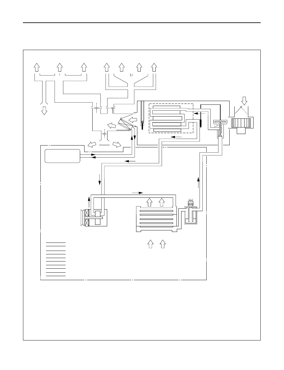
AIR CONDITIONING REFRIGERANT CYCLE CONSTRUCTION
,
,
,,,
,,
,
,
,,
,,
,,,,,,,,,
,,,,,,,,,
,,,,,,,,,
,,,,,,,,
,,,,,,,,
,,,,,,,,
,
,,
,
,,,
,,,
,,,,,
,,,,,
,
,
15
14
11
12
13
16
10
17
7
3
4
5
2
1
8
9
6
13
Side vent
Lap vent
Outside air
Engine
Side vent
Cooling air
High pressure, high temperature gas
High pressure, high temperature
mixture of gas and liquid
Low pressure, low temperature
mixture of liquid and gas
Low pressure, low temperature gas
High pressure, medium temperature liquid
Side defrost
Side defrost
Defrost
Center vent
GENERAL DESCRIPTION
1.
Compressor
2.
Magnetic clutch
3.
Receiver/Drier
4.
Dual pressure switch
5.
Condenser
6.
Evaporator assembly
7.
Expansion valve
8.
Temperature sensor
9.
Evaporator core
10. Blower motor
11. Heater unit
12. Heater core
13. Temp. control door (Air mix door)
14. Mode (DEF) control door
15. Mode (VENT) control door
16. Mode (HEAT) control door
17. Electronic thermostat
1B – 4 AIR CONDITIONING
The refrigeration cycle includes the following four
processes as the refrigerant changes repeatedly
from liquid to gas and back to liquid while
circulating.
EVAPORATION
The refrigerant is changed from a liquid to a gas
inside the evaporator. The refrigerant mist that
enters the evaporator vaporizes readily. The liquid
refrigerant removes the required quantity of heat
(latent heat of vaporization) from the air around the
evaporator core cooling fins and rapidly vaporizes.
Removing the heat cools the air, which is then
radiated from the fins and lowers the temperature
of the air inside the vehicle.
The refrigerant liquid sent from the expansion valve
and the vaporized refrigerant gas are both present
inside the evaporator and the liquid is converted to
gas.
With this change from liquid to gas, the pressure
inside the evaporator must be kept low enough for
vaporization to occur at a lower temperature.
Because of that, the vaporized refrigerant is sucked
into the compressor.
COMPRESSION
The refrigerant is compressed by the compressor
until it is easily liquefied at normal temperature.
The vaporized refrigerant in the evaporator is
sucked into the compressor. This action maintains
the refrigerant inside the evaporator at a low
pressure so that it can easily vaporize, even at low
temperatures close to 0°C (32°F).
Also, the refrigerant sucked into the compressor is
compressed inside the cylinder to increase the
pressure and temperature to values such that the
refrigerant can easily liquefy at normal ambient
temperatures.
CONDENSATION
The refrigerant inside the condenser is cooled by
the outside air and changes from gas to liquid.
The high temperature, high pressure gas coming
from the compressor is cooled and liquefied by the
condenser with outside air and accumulated in the
receiver/drier. The heat radiated to the outside air
by the high temperature, high pressure gas in the
compressor is called heat of condensation. This is
the total quantity of heat (heat of vaporization) the
refrigerant removes from the vehicle interior via the
evaporator and the work (calculated as the quantity
of heat) performed for compression.
EXPANSION
The expansion valve lowers the pressure of the
refrigerant liquid so that it can easily vaporize.
The process of lowering the pressure to encourage
vaporization before the liquefied refrigerant is sent
to the evaporator is called expansion. In addition,
the expansion valve controls the flow rate of the
refrigerant liquid while decreasing the pressure.
That is, the quantity of refrigerant liquid vaporized
inside the evaporator is determined by the quantity
of heat which must be removed at a prescribed
vaporization temperature. It is important that the
quantity of refrigerant be controlled to exactly the
right value.
COMPRESSOR
The compressor performs two main functions:
It compresses low-pressure and low-temperature
refrigerant vapor from the evaporator into high-
pressure and high-temperature refrigerant vapor to
the condenser. And it pumps refrigerant and
refrigerant oil through the A/C system.
6VD1/6VE1 engine on RHD model is equipped with
an invariable capacity five-vane rotary compressor
(DKV-14D Type).
The compressor sucks and compresses refrigerant
by the rotation of the vane installed to the shaft,
and always discharges a fixed amount of refrigerant
independent of the load of refrigerant.
The thermo sensor is installed to the front head of
the compressor to protect it by stopping its
operation when the refrigerant gas is insufficient or
when the temperature is abnormally high.
•
OFF . ... 160
±
5°C (320.0
±
41°F)
•
ON . . 135
±
5°C (275.0
±
41°F)
Diesel Engine models and 6VD1/6VE1 engine on
LHD model are equipped with a swash plate type
compressor
Swash plate compressors have a swash (slanted)
plate mounted on the shaft. When the shaft turns,
the rotation of the swash plate is converted to
reciprocating piston motion which sucks in and
compresses the refrigerant gas.
Shaft seal (Lip type) is installed between the valve
plate and shaft & cylinder head to prevent
refrigerant gas leaks. A specified amount of
compressor oil is contained in the oil pan.
This oil is supplied to the cylinders, bearings, etc.,
by an oil pump which is connected to the swash
plate shaft.
Нет комментариевНе стесняйтесь поделиться с нами вашим ценным мнением.
Текст