Opel Frontera UBS. Service manual — part 2423
6E–6
4JX1–TC ENGINE DRIVEABILITY AND EMISSIONS
Removal Procedure
6E–212
. . . . . . . . . . . . . . . . . . . .
Installation Procedure
6E–212
. . . . . . . . . . . . . . . . . .
Fuel Filter Cap
6E–213
. . . . . . . . . . . . . . . . . . . . . . . . . .
General Description
6E–213
. . . . . . . . . . . . . . . . . . . .
Inspection Procedure
6E–213
. . . . . . . . . . . . . . . . . .
Fuel Filter
6E–213
. . . . . . . . . . . . . . . . . . . . . . . . . . . . . .
Removal and Installation Procedure
6E–213
. . . . . .
Fuel Gauge Unit
6E–213
. . . . . . . . . . . . . . . . . . . . . . . .
Removal Procedure
6E–213
. . . . . . . . . . . . . . . . . . . .
Installation Procedure
6E–214
. . . . . . . . . . . . . . . . . .
Fuel Injectors
6E–214
. . . . . . . . . . . . . . . . . . . . . . . . . . .
Removal and Installation Procedure
6E–214
. . . . . .
Fuel Temperature Sensor
6E–214
. . . . . . . . . . . . . . . .
Removal Procedure
6E–214
. . . . . . . . . . . . . . . . . . . .
Installation Procedure
6E–215
. . . . . . . . . . . . . . . . . .
Rail Pressure (RP) Sensor
6E–216
. . . . . . . . . . . . . . .
Removal Procedure
6E–216
. . . . . . . . . . . . . . . . . . . .
Installation Procedure
6E–216
. . . . . . . . . . . . . . . . . .
Fuel Tank
6E–216
. . . . . . . . . . . . . . . . . . . . . . . . . . . . . .
Removal Procedure
6E–216
. . . . . . . . . . . . . . . . . . . .
Throttle Body (TB)
6E–217
. . . . . . . . . . . . . . . . . . . . . . .
Removal Procedure
6E–217
. . . . . . . . . . . . . . . . . . . .
Installation Procedure
6E–217
. . . . . . . . . . . . . . . . . .
Air Conditioning (A/C) Relay
6E–217
. . . . . . . . . . . . . .
Removal Procedure
6E–217
. . . . . . . . . . . . . . . . . . . .
Installation Procedure
6E–217
. . . . . . . . . . . . . . . . . .
Exhaust Gas Recirculation (EGR) Vacuum
Switch Valve (VSV)
6E–217
. . . . . . . . . . . . . . . . . . . . .
Removal Procedure
6E–217
. . . . . . . . . . . . . . . . . . . .
Installation Procedure
6E–218
. . . . . . . . . . . . . . . . . .
Electronic Vacuum Regurating Valve (EVRV)
6E–219
Removal Procedure
6E–219
. . . . . . . . . . . . . . . . . . . .
Installation Procedure
6E–220
. . . . . . . . . . . . . . . . . .
Wiring and Connectors
6E–220
. . . . . . . . . . . . . . . . . . .
Wiring Harness Service
6E–220
. . . . . . . . . . . . . . . .
Connectors and Terminals
6E–220
. . . . . . . . . . . . . .
Wire Harness Repair: Twisted Shielded
Cable
6E–220
. . . . . . . . . . . . . . . . . . . . . . . . . . . . . . . . .
Removal Procedure
6E–220
. . . . . . . . . . . . . . . . . . . .
Installation Procedure
6E–221
. . . . . . . . . . . . . . . . . .
Twisted Leads
6E–221
. . . . . . . . . . . . . . . . . . . . . . . . . .
Removal Procedure
6E–221
. . . . . . . . . . . . . . . . . . . .
Installation Procedure
6E–222
. . . . . . . . . . . . . . . . . .
Weather-Pack Connector
6E–223
. . . . . . . . . . . . . . . . .
Tools Required
6E–223
. . . . . . . . . . . . . . . . . . . . . . . .
Removal Procedure
6E–223
. . . . . . . . . . . . . . . . . . . .
Installation Procedure
6E–223
. . . . . . . . . . . . . . . . . .
Com-Pack III
6E–224
. . . . . . . . . . . . . . . . . . . . . . . . . . .
General Information
6E–224
. . . . . . . . . . . . . . . . . . . .
Metri-Pack
6E–224
. . . . . . . . . . . . . . . . . . . . . . . . . . . . .
Tools Required
6E–224
. . . . . . . . . . . . . . . . . . . . . . . .
Removal Procedure
6E–224
. . . . . . . . . . . . . . . . . . . .
Installation Procedure
6E–224
. . . . . . . . . . . . . . . . . .
General Description
(ECM and Sensors)
6E–225
. . . . . . . . . . . . . . . . . . . . .
57X Reference ECM Input
6E–225
. . . . . . . . . . . . . .
A/C Request Signal
6E–225
. . . . . . . . . . . . . . . . . . . .
Crankshaft Position (CKP) Sensor
6E–225
. . . . . . .
Camshaft Position (CMP) Sensor and
Signal
6E–225
. . . . . . . . . . . . . . . . . . . . . . . . . . . . . . .
Engine Coolant Temperature (ECT) Sensor
6E–225
Electrically Erasable Programmable Read
Only Memory (EEPROM)
6E–225
. . . . . . . . . . . . . .
Intake Air Temperature (IAT) Sensor
6E–225
. . . . .
Manifold Absolute Pressure (MAP) Sensor
6E–226
Engine Control Module (ECM)
6E–226
. . . . . . . . . . .
ECM Function
6E–226
. . . . . . . . . . . . . . . . . . . . . . . . .
ECM Components
6E–226
. . . . . . . . . . . . . . . . . . . . .
ECM Voltage Description
6E–226
. . . . . . . . . . . . . . .
ECM Input/Outputs
6E–226
. . . . . . . . . . . . . . . . . . . .
ECM Service Precautions
6E–227
. . . . . . . . . . . . . .
Intake Throttle Position (ITP) Sensor
6E–227
. . . . .
Transmission Range Switch
6E–227
. . . . . . . . . . . . .
Accelerator Position Sensor (AP)
6E–227
. . . . . . . .
Aftermarket Electrical and Vacuum
Equipment
6E–227
. . . . . . . . . . . . . . . . . . . . . . . . . . .
Electrostatic Discharge Damage
6E–227
. . . . . . . . .
General Description (Air Induction)
6E–228
. . . . . . . .
Air Induction System
6E–228
. . . . . . . . . . . . . . . . . . .
General Description (Fuel Metering)
6E–228
. . . . . . .
Deceleration Mode
6E–228
. . . . . . . . . . . . . . . . . . . .
Fuel Injector
6E–228
. . . . . . . . . . . . . . . . . . . . . . . . . .
Fuel Metering System Components
6E–228
. . . . . .
A/C Clutch Diagnosis
6E–228
. . . . . . . . . . . . . . . . . . . .
A/C Request Signal
6E–228
. . . . . . . . . . . . . . . . . . . .
General Description Exhaust Gas
Recirculation (EGR) System
6E–228
. . . . . . . . . . . . .
EGR Purpose
6E–228
. . . . . . . . . . . . . . . . . . . . . . . . .
Fuse and Relay Panel
(Underhood Electrical Center) RHD
6E–229
. . . . . . .
Fuse and Relay Panel
(Underhood Electrical Center) LHD
6E–230
. . . . . . .

6E–7
4JX1–TC ENGINE DRIVEABILITY AND EMISSIONS
Specification
Tightening Specifications
Application
N·m
Kg·m
Lb Ft.
Lb In.
Camshaft Position Sensor Retaining Screw
9
0.9
—
78
Crankshaft Position Sensor Mounting Bolt
9
0.9
—
78
Engine Coolant Temperature Sensor
19
1.9
14
—
Throttle Body Mounting Nuts
20
2.0
14
—
VSS Retaining Bolt
16
1.6
12
—
MAP Sensor Screw
4
0.4
—
35
EGR VSV Bolts
8
0.8
—
69
Fuel Temp Sensor
19
1.9
14
—
Oil Temp Sensor Bolt
19
1.9
14
—
Rail Pressure Sensor Bolt
20
2.0
14
—
6E–8
4JX1–TC ENGINE DRIVEABILITY AND EMISSIONS
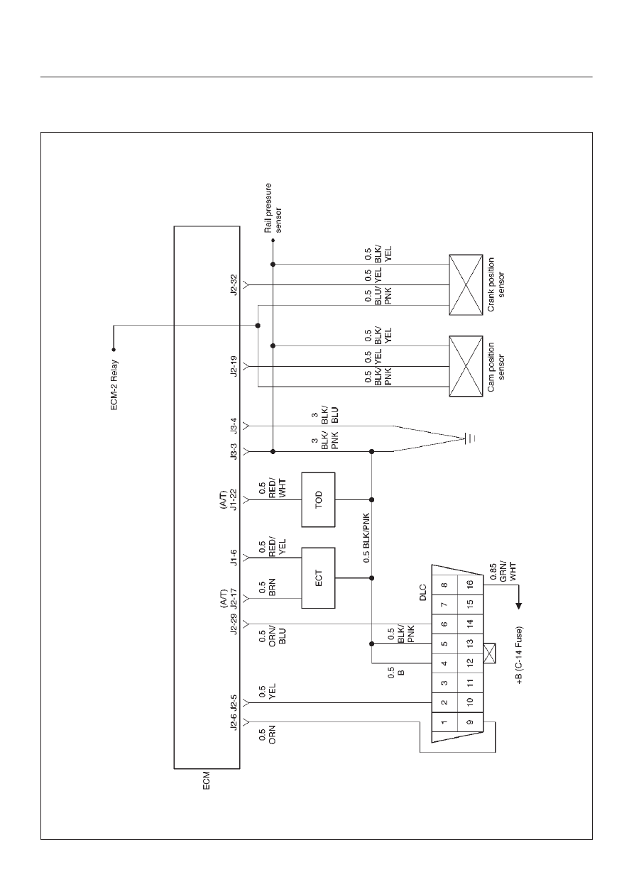
Diagrams and Schematics
ECM Wiring Diagram (1 of 6)
060RW127
6E–9
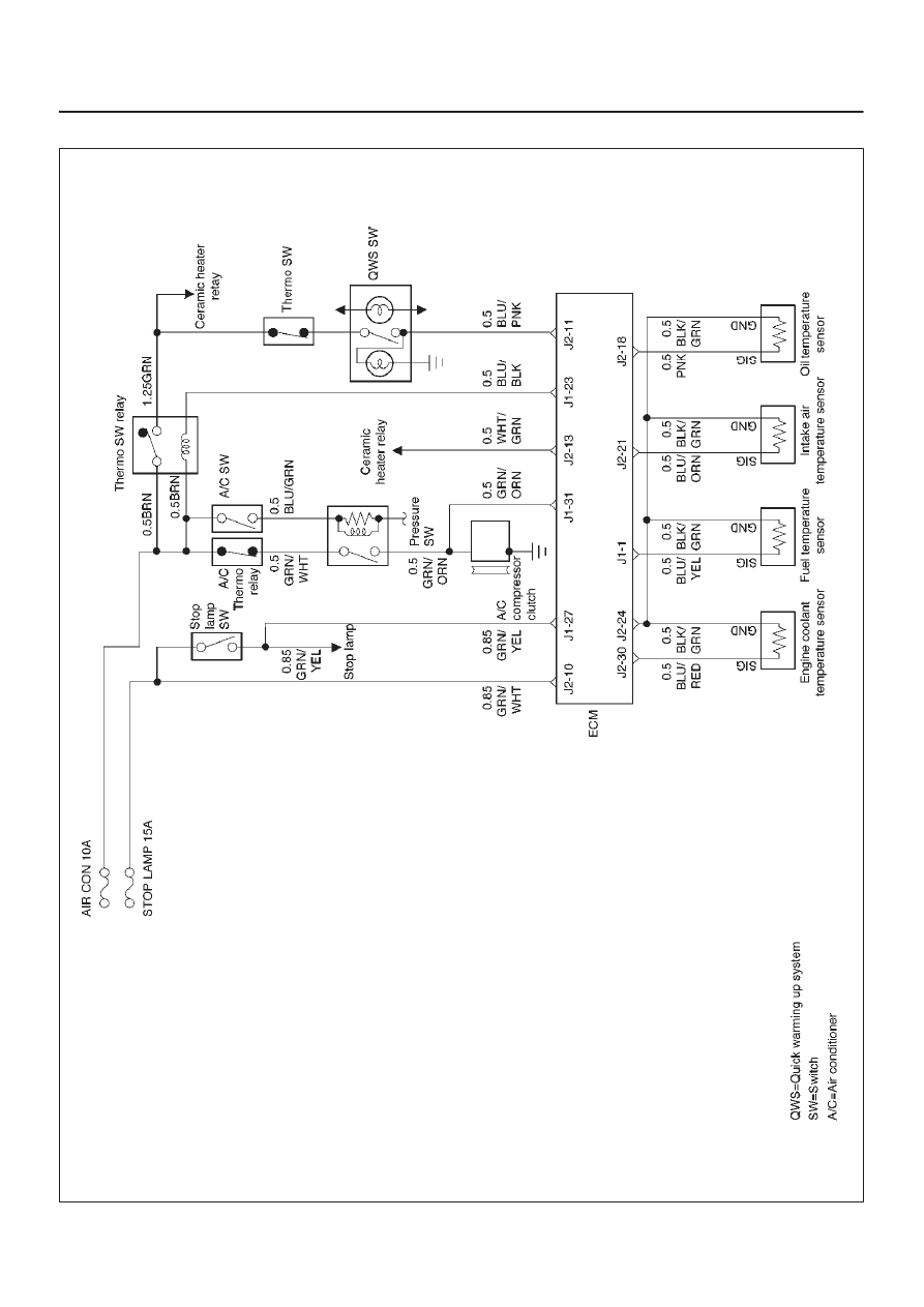
4JX1–TC ENGINE DRIVEABILITY AND EMISSIONS
ECM Wiring Diagram (2 of 6)
060RW125
Нет комментариевНе стесняйтесь поделиться с нами вашим ценным мнением.
Текст