Opel Frontera UBS. Service manual — part 1173

6E–58
ENGINE DRIVEABILITY AND EMISSIONS
A/C Clutch Control Circuit Diagnosis
(Cont'd)
Step
No
Yes
Value(s)
Action
34
1. Remove the A/C compressor relay.
2. Ignition “ON.”
3. Use a DVM to check voltage at both of the BRN
wires at the A/C compressor relay socket.
Is the voltage equal to the specified value?
+B
Go to
Step 36
Go to
Step 35
35
Repair the faulty BRN wire between the A/C fuse and
the A/C compressor relay .
Is the action complete?
—
Verify repair
—
36
1. A/C compressor relay removed.
2. Engine idling.
3. A/C “ON.”
4. Blower “ON.”
5. Use a DVM to measure voltage between the
GRN/BLK wire at the A/C compressor relay socket
and battery
±
.
Did the DVM indicate the specified value?
+B
Go to
Step 40
Go to
Step 37
37
Check for an open GRN/BLK wire between PCM
terminal B-14 and the A/C compressor relay.
Was the wire open?
—
Go to
Step 38
Go to
Step 39
38
Repair the open GRN/BLK wire between the PCM and
the A/C compressor relay.
Is the action complete?
—
Verify repair
—
39
Check for a damaged pin or terminal at B-14 of the
PCM.
Was a damaged pin or a terminal found?
—
Go to
Step 32
Go to
Step 33
40
1. A/C compressor relay removed.
2. Connect a fused jumper at the A/C compressor
relay socket between either BRN wire and the
BRN/YEL wire.
3. Engine idling.
4. A/C “ON.”
5. Blower “ON.”
Did the compressor magnetic clutch engage?
—
Go to
Step 41
Go to
Step 42
41
Repair the A/C compressor relay.
Is the action complete?
—
Verify repair
—
42
Check for an open circuit between the A/C compressor
relay and the A/C clutch.
Was an open circuit found?
—
Go to
Step 43
Go to
Step 44
43
Repair the open circuit between the compressor Clutch
and the A/C compressor relay.
Is the action complete?
—
Verify repair
—
44
Service the compressor clutch or replace the
compressor due to a faulty internal overheat switch.
Is the action complete?
—
Verify repair
—

6E–59
ENGINE DRIVEABILITY AND EMISSIONS
A/C Clutch Control Circuit Diagnosis
(Cont'd)
Step
No
Yes
Value(s)
Action
45
1. Remove the A/C compressor relay.
2. Idle the engine.
Is the compressor clutch still engaged when A/C is not
selected?
—
Go to
Step 46
Go to
Step 47
46
Repair the short to voltage between the A/C clutch and
A/C compressor relay.
Is the action complete?
—
Verify repair
—
47
1. Reinstall the A/C compressor relay.
2. Remove the A/C thermostat relay.
3. Engine idling.
Is the compressor clutch still engaged when A/C is not
selected?
—
Go to
Step 48
Go to
Step 50
48
Use a DVM to check for a short to ground between the
A/C compressor relay and B-14 of the PCM.
Was a short detected?
—
Go to
Step 49
Go to
Step 33
49
Repair the short to ground between the PCM and A/C
compressor relay.
Is the action complete?
—
Verify repair
—
50
Repair the short to ground between the A/C thermostat
relay and the electronic thermostat.
Is the action complete?
—
Verify repair
—
6E–60
ENGINE DRIVEABILITY AND EMISSIONS
Electronic Ignition System Diagnosis
If the engine cranks but will not run or immediately stalls,
the Engine Cranks But Will Not Start chart must be used
to determine if the failure is the ignition system or the fuel
system. If DTC P0341, or P0336 is set, the appropriate
diagnostic trouble code chart must be used for diagnosis.
If a misfire is being experienced with no DTC set, refer to
the
Symptoms section for diagnosis.
Fuel Metering System Check
Some failures of the fuel metering system will result in an
“Engine Cranks But Will Not Run” symptom. If this
condition exists, refer to the
Cranks But Will Not Run
chart. This chart will determine if the problem is caused
by the ignition system, the PCM, or the fuel pump
electrical circuit.
Refer to
Fuel System Electrical Test for the fuel system
wiring schematic.
If there is a fuel delivery problem, refer to
Fuel System
Diagnosis, which diagnoses the fuel injectors, the fuel
pressure regulator, and the fuel pump. If a malfunction
occurs in the fuel metering system, it usually results in
either a rich HO2S signal or a lean HO2S signal. This
condition is indicated by the HO2S voltage, which causes
the PCM to change the fuel calculation (fuel injector pulse
width) based on the HO2S reading. Changes made to the
fuel calculation will be indicated by a change in the long
term fuel trim values which can be monitored with a Tech
2. Ideal long term fuel trim values are around 0%; for a
lean HO2S signal, the PCM will add fuel, resulting in a fuel
trim value above 0%. Some variations in fuel trim values
are normal because all engines are not exactly the same.
If the fuel trim values are greater than +23%, refer to
DTC
P0131, DTC P0151, DTC P0171, and DTC 1171 for items
which can cause a lean HO2S signal.
Idle Air Control (IAC) Valve
The Tech 2 displays the IAC pintle position in counts. A
count of “0” indicates the PCM is commanding the IAC
pintle to be driven all the way into a fully-seated position.
This is usually caused by a large vacuum leak.
The higher the number of counts, the more air is being
commanded to bypass the throttle blade. Refer to IAC
System Check in order to diagnose the IAC system.
Refer to
Rough, Unstable, or Incorrect Idle, Stalling in
Symptoms for other possible causes of idle problems.
Fuel System Pressure Test
A fuel system pressure test is part of several of the
diagnostic charts and symptom checks. To perform this
test, refer to
Fuel Systems Diagnosis.
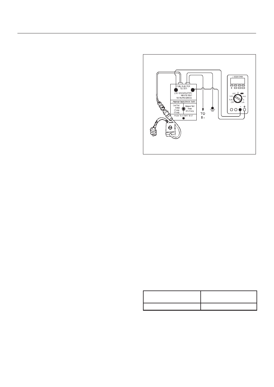
Fuel Injector Coil Test Procedure and
Fuel Injector Balance Test Procedure
T32003
Test Description
Number(s) below refer to the step number(s) on the
Diagnostic Chart:
2. Relieve the fuel pressure by connecting the
5-8840-0378-0 Fuel Pressure Gauge to the fuel
pressure connection on the fuel rail.
CAUTION: In order to reduce the risk of fire and
personal injury, wrap a shop towel around the fuel
pressure connection. The towel will absorb any fuel
leakage that occurs during the connection of the fuel
pressure gauge. Place the towel in an approved
container when the connection of the fuel pressure
gauge is complete.
Place the fuel pressure gauge bleed hose in an
approved gasoline container.
With the ignition switch “OFF,” open the valve on the
fuel pressure gauge.
3. Record the lowest voltage displayed by the DVM
after the first second of the test. (During the first
second, voltage displayed by the DVM may be
inaccurate due to the initial current surge.)
Injector Specifications:
Resistance Ohms
Voltage Specification at
10
°
C-35
°
C (50
°
F-95
°
F)
11.8 – 12.6
5.7 – 6.6
D
The voltage displayed by the DVM should be within
the specified range.
D
The voltage displayed by the DVM may increase
throughout the test as the fuel injector windings
warm and the resistance of the fuel injector windings
changes.
6E–61
ENGINE DRIVEABILITY AND EMISSIONS
D
An erratic voltage reading (large fluctuations in
voltage that do not stabilize) indicates an
intermittent connection within the fuel injector.
5. Injector Specifications:
Highest Acceptable
Voltage Reading
Above/Below 35
°
C/10
°
C
(95
°
F/50
°
F)
Acceptable Subtracted
Value
9.5 Volts
0.6 Volts
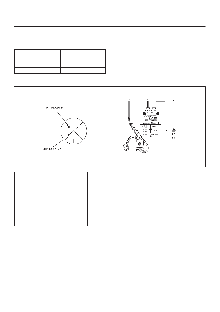
7. The Fuel Injector Balance Test portion of this chart
(Step 7 through Step 11) checks the mechanical
(fuel delivery) portion of the fuel injector. An engine
cool-down period of 10 minutes is necessary in
order to avoid irregular fuel pressure readings due
to “Hot Soak” fuel boiling.
Injector Coil Test Procedure (Steps 1-6) and Injector Balance Test Procedure (Steps 7-11)
R262001
CYLINDER
1
2
3
4
5
6
1st Reading (1)
296 kPa
(43 psi)
296 kPa
(43 psi)
296 kPa
(43 psi)
296 kPa
(43 psi)
296 kPa
(43 psi)
296 kPa
(43 psi)
2nd Reading (2)
131 kPa
(19 psi)
117 kPa
(17 psi)
124 kPa
(18 psi)
145 kPa
(21 psi)
131 kPa
(19 psi)
130 kPa
(19 psi)
Amount of Drop (1st
Reading–2nd Reading)
165 kPa
(24 psi)
179 kPa
(26 psi)
172 kPa
(25 psi)
151 kPa
(22 psi)
165 kPa
(24 psi)
166 kPa
(24 psi)
Av.drop = 166 kPa/24 psi
±
10 kPa/1.5 psi
= 156 – 176 kPa or
22.5 – 25.5 psi
OK
Faulty, Rich
(Too Much
Fuel Drop)
OK
Faulty, Lean
(Too Little
Fuel Drop)
OK
OK
NOTE: These figures are examples only.
Нет комментариевНе стесняйтесь поделиться с нами вашим ценным мнением.
Текст