Opel Frontera UBS. Service manual — part 439
6A – 46 ENGINE MECHANICAL
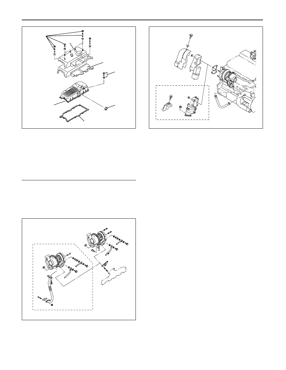
Legend
(1) Cylinder Head Noise Insulator Cover
(2) Insulator
(3) Bolt
(4) Oil Seal
(5) Gasket
(6) Cylinder Head Cover
(7) Bolt, Stud and Rubber Mounting
21. Install water hose between thermostat and radiator.
22. Install turbocharger assembly to exhaust manifold.
Torque: 27 N·m (2.8 kg·m/20.2 lb ft)
23. Install water hose and oil pipe for turbocharger.
24. Install exhaust valve assembly and heat protector.
Torque: 27 N·m (2.8 kg·m/20.2 lb ft) for valve
Torque: 9 N·m (0.9 kg·m/6.5 lb ft) for heat protector
25. Install generator assembly.
Torque: 40 N·m (4.0 kg·m/29 lb ft) for ACG bracket
Torque: 40 N·m (4.0 kg·m/29 lb ft) between ACG and
bracket
Torque: 20 N·m (2.0 kg·m/14.5 lb ft) between ACG
and adjuster plate
26. Fix the A/C compressor bracket and install A/C
compressor.
Torque: 47 N·m (4.7 kg·m/34 lb ft) for A/C bracket
Torque: 20 N·m (2.0 kg·m/14.5 lb ft) for belt tensioner
27. Reconnect harness connector around cylinder
head.
28. Connect EGR vacuum hose.
29. Install oil level gauge guide assembly.
Tighten nuts lower portion and tighten bolt.
Torque: 20 N·m (2.0 kg·m/14.5 lb ft)
30. Install intercooler assembly.
Refer to “Intercooler” in this manual.
31. Install air duct between air cleaner and
turbocharger.
32. Fill engine coolant.
33. Reconnect battery.
For Europe
025R200007
For Europe
025R200006
1
7
2
3
4
5
6
010R200006
ENGINE MECHANICAL 6A – 47
CAMSHAFT
2
1
6
With
spacer type
Without
spacer type
13
14
8
12
11
10
9
3
4
7
5
012R200004
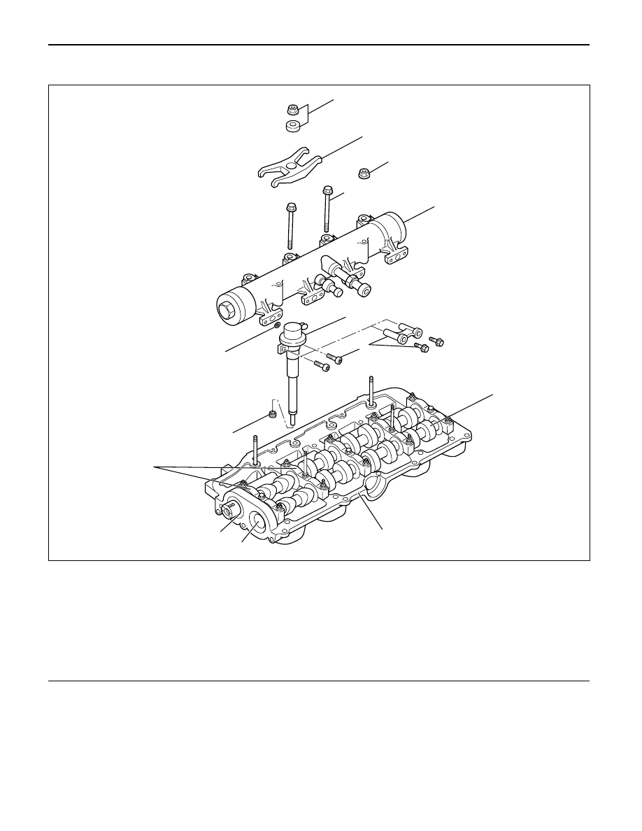
Legend
(1)
Nut and Washer
(2)
Injector Clamp
(3)
Nut
(4)
Bolt
(5)
Oil Rail Assembly
(6)
Spacer (If equipped) and Bolt
(7)
Injector Assembly
(8)
Camshaft
(9)
Camshaft Carrier
(10)
Plug
(11)
Oil Seal
(12)
Camshaft Bracket
(13)
Gasket
(14)
Gasket
6A – 48 ENGINE MECHANICAL
DISASSEMBLY
1. Injector clamp
2. Injector assembly
3. Oil rail assembly
4. Camshaft bracket
5. Camshaft
6. Oil seal
7. Plug
NOTE: Before starting disassembly above, drain oil
from oil rail to prevent oil from entering the cylinder.
REASSEMBLY
1. Camshaft
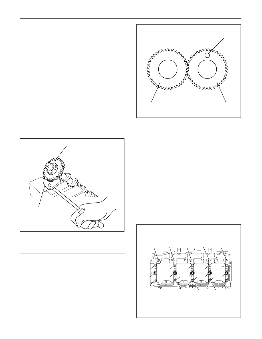
1) Before reassembling the camshaft to the
camshaft carrier, align the holes between the
main gear and the sub gear on the intake side of
the camshaft gear with a special tool.
2) Set lock pin to gear holes from sub gear side.
Camshaft Gear Tool: 5-8840-2591-0
Legend
(1) Locking pin
(2) Special tool
3) Apply engine oil to the camshaft gear tooth.
4) Apply engine oil to the journal on the camshaft
carrier.
5) Align the timing mark on the intake and exhaust
camshaft gear and put on the camshaft carrier.
Legend
(1) Locking pin
(2) Intake side camshaft gear
(3) Exhaust side camshaft gear
6) Apply liquid gasket (TB1207B or equivalent) to
No. 1 camshaft bracket matching surface.
7) Set No. 1 to No. 5 camshaft bracket on camshaft
carrier.
8) Temporarily tighten bracket bolts B and C.
Temporal Torque: 20 N·m (2.0 kg·m/14.5 lb ft)
9) Put gasket on the cylinder head.
10) Install camshaft carrier onto the cylinder head
and tighten bolts to specified torque.
Torque: A; 22 N·m (2.2 kg·m/15.9 lb ft)
B; 38 N·m (3.9 kg·m/28.2 lb ft)
C; 22 N·m (2.2 kg·m/15.9 lb ft)
D; 38 N·m (3.9 kg·m/28.2 lb ft)
•
Remove locking pin.
1
2
014RW183
3
2
1
014RW184
C
C
D
B
C
C
B
C
C
D
C
C
B
C
A
A
A
A
A
A
A
A
A
A
011RW035
ENGINE MECHANICAL 6A – 49
INSPECTION AND REPAIR
Make the necessary adjustments, repairs, and part
replacements if excessive wear or damage is
discovered during inspection.
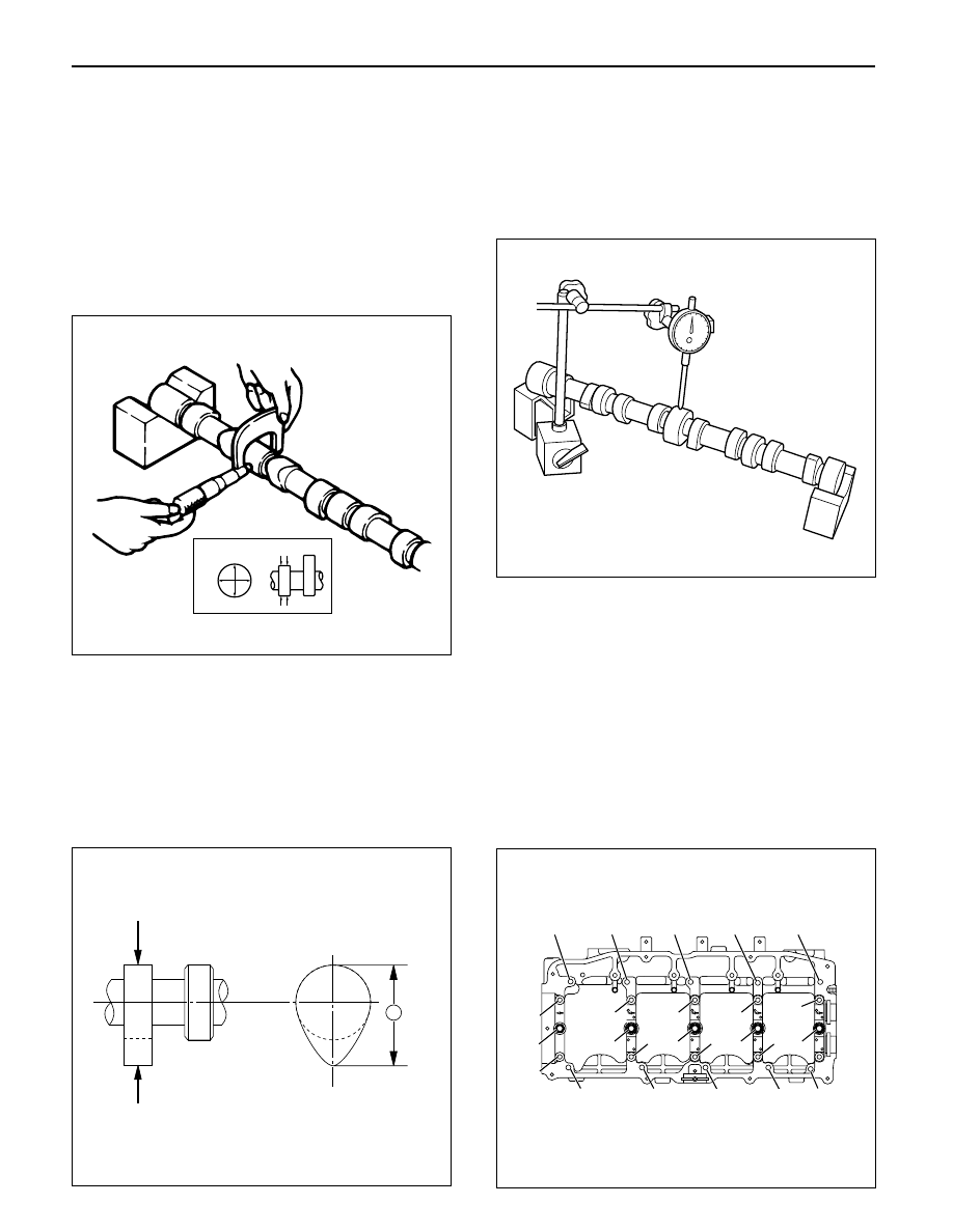
1. Camshaft Journal diameter
1) Use a micrometer to measure each camshaft
journal diameter in two directions (1) and (2). If
the measured value is less than the specified
limit, the camshaft must be replaced.
Standard: 29.939 – 29.96 mm (1.1787 – 1.1795 in)
Limit: 29.84 mm (1.17 in)
2. Cam Height
1) Measure the cam height (H) with a micrometer.
If the measured value is less than the specified
limit, the camshaft must be replaced.
Standard: IN
46.62 mm (1.8354 in)
EX 46.72 mm (1.8394 in)
Limit: IN
46.57 mm (1.8335 in)
EX 46.67 mm (1.8374 in)
3. Cam Run-Out
1) Mount the camshaft on V-blocks.
2) Measure the cam height (H) with a micrometer.
If the measured value is less than the specified
limit, the camshaft must be replaced.
Standard: 0.02 mm (0.0008 in) or less
Limit: 0.10 mm (0.0039 in)
4. Camshaft oil clearance
1) Clean the camshaft, camshaft bracket and
camshaft carrier.
2) Put camshaft carrier on the cylinder head.
3) Put camshaft on the camshaft carrier.
4) Put plastigauge on the camshaft journal.
5) Install camshaft bracket to original position and
tighten bolts to specified torque in the numerical
order shown in the illustration.
Torque: A; 22 N·m (2.2 kg·m/15.9 lb ft)
B; 38 N·m (3.9 kg·m/28.2 lb ft)
C; 22 N·m (2.2 kg·m/15.9 lb ft)
D; 38 N·m (3.9 kg·m/28.2 lb ft)
(1)
Ft Rr
(2)
014RW179
H
012RW059
014RW171
C
C
D
B
C
C
B
C
C
D
C
C
B
C
A
A
A
A
A
A
A
A
A
A
110RW035
Нет комментариевНе стесняйтесь поделиться с нами вашим ценным мнением.
Текст