Opel Frontera UBS. Service manual — part 2495
7A–30
AUTOMATIC TRANSMISSION (4L30–E)
Removal
1. Disconnect battery ground cable.
2. Remove transfer control lever knob.
3. Remove front console.
D
Disconnect wiring harness connectors from front
console.
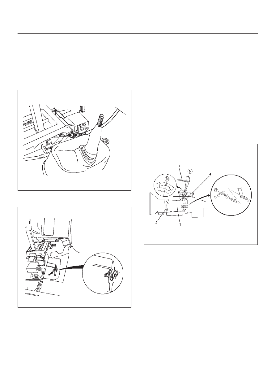
4. Disconnect shift lock cable (1) from the selector lever
assembly side.
256RW012
5. Disconnect shift control rod (2) from the selector lever
assembly side.
256RW013
6. Disconnect wiring harness connectors from the
selector lever assembly.
7. Remove selector lever assembly.
Installation
To install, follow the removal steps in the reverse order,
noting the following points:
Adjustment of select lever and control rod
1. Place the vehicle on a level surface.
NOTE: If the vehicle is not on level surface, the shift
select cable set positions will vary with the movement of
engine. To prevent possible misadjustment of the cable,
the vehicle must be placed on a level surface.
2. Install the shift control rod (1) to the transmission
select lever (2), and then place the lever in the “N”
position.
3. Set select lever in the “N” position.
4. Push select lever forward (“R” position side) and
secure it (using a rubber band (3), etc.) so that the pin
comes into contact with the wall of the detent plate.
5. Install the shift control rod (1) to the selector lever arm
(4).
Torque: 32 N
•
m (3.3 kg·m/24 lb ft)
NOTE: Do not apply oil to the threaded portions.
256RW014
6. After adjustment, make sure that the selector lever
operates normally, and that each selector position is
properly indicated. (The red mark shows through the
window.)
Adjustment of shift lock cable
1. Set ignition key in “LOCK” position and selector lever
in “P” position.
2. Adjust cable screw cap on selector lever side to
provide a gap (slack for cable) of 1 – 2 mm between
rod on steering lock side and stopper.
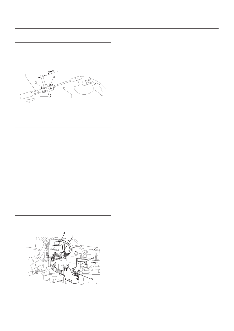
Adjust cap as follows:
a. Pull screw cap (1) in arrow direction to remove
inner cable slack.
b. With cable kept as (a), adjust gap between nut (2)
and bracket to 5 mm (0.2 in).
c. Lock inner cable by turning nut (3) while holding nut
(2) in place.
Torque : 3.7 N
•
m (38 kg·cm/33 lb in)
7A–31
AUTOMATIC TRANSMISSION (4L30–E)
NOTE: Clean the cable threads, and do not apply oil to
them.
256RW015
3. Check the shift lock operation:
a. Selector lever should not move out of “P” position
with ignition key in “Lock” position.
b. Selector lever can be moved out of “P” position with
ignition key in “ON” position only when brake pedal
is depressed.
c. Ignition key can be turned to “LOCK” position only
when selector lever is in “P” position (key can be
pulled out).
If (a) and (c) fail, readjust cable. If (b) fails, readjust
connector wiring and brake pedal switch.
Mode Switch
Removal
1. Place selector lever in neutral.
2. Disconnect battery ground cable.
3. Remove mode switch cover (1).
4. Disconnect selector lever (2) from the mode switch.
5. Disconnect transmission harness from the mode
switch connector (3).
6. Remove bracket with mode switch connector from
the transmission case.
7. Remove mode switch connector (3) from the bracket
(4).
8. Remove two mode switch bolts and nut then remove
mode switch (5).
210RW008
Installation
To install, follow the removal steps in the reverse order,
noting the following points;
1. Torque
Mode switch bolt: 13 N
•
m (1.3 kg·m/113 lb in)
Selector lever nut: 23 N
•
m (2.3 kg·m/17 lb ft)
2. Mode switch setting procedure
Perform either of the following adjustment
procedures:
Procedure 1
a. Place selector lever in neutral.
b. Remove selector lever from the mode switch.
c. Remove the mode switch cover.
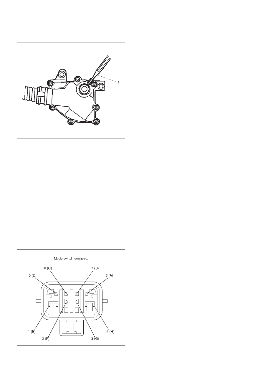
d. Loosen the two 10 mm screws.
e. Rotate the mode switch until the slot in the mode
switch housing aligns with the selector shaft
bushing, and insert a 3/32 in. (2.4 mm) drill bit or
punch (1) into the slot.
f. Tighten the screws to 13 N·m (1.3 kg·m/113 lb in).
g. After completing adjustment, snap the mode
switch cover into place.
7A–32
AUTOMATIC TRANSMISSION (4L30–E)
h. Reinstall the selector lever.
249RW001
Procedure 2
a. Place selector lever in neutral.
b. Disconnect transmission harness connector from
mode switch connector.
c. Remove mode switch connector with bracket from
the transmission case.
d. Connect multimeter (resistance mode) to
terminals 1(E) and 4(H) on mode switch connector.
e. Loosen two mounting screws.
f. Rotate mode switch slightly in both directions to
determine the range (approx. 5 degrees) of
electrical contact.
g. Position mode switch in middle of contact range.
h. Tighten two mounting screws.
i. Remove multimeter and install mode switch
harness connector with bracket to the
transmission case.
j. Connect transmission harness connector to mode
switch connector.
F07RW003
7A–33
AUTOMATIC TRANSMISSION (4L30–E)
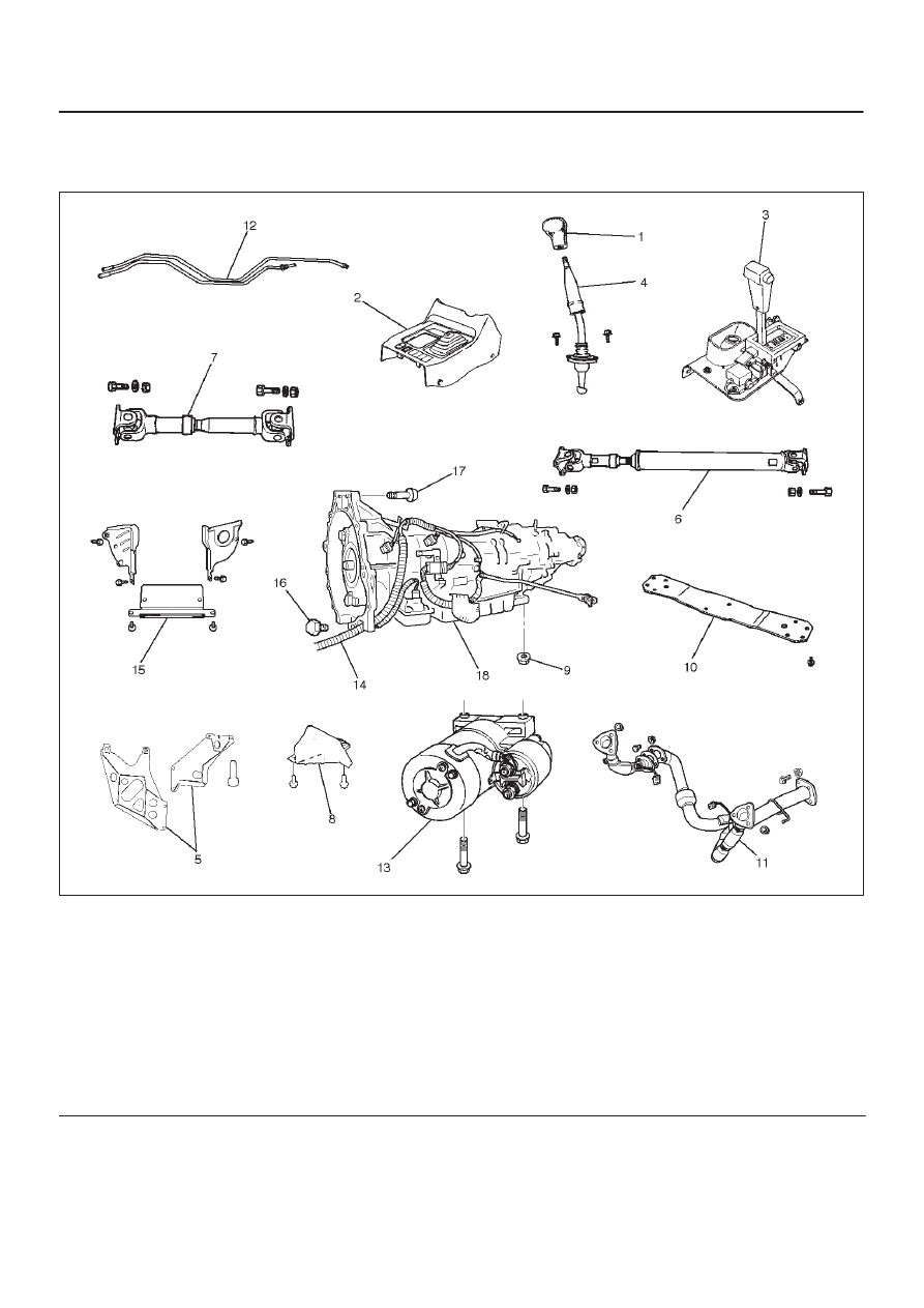
Transmission (With Transfer Case)
Transmission And Associated Parts
240RW027
Legend
(1) Transfer Control Lever Knob
(2) Front Console
(3) Selector Lever Assembly
(4) Transfer Control Lever
(5) Transfer and Exhaust Protector
(6) Rear Propeller Shaft
(7) Front Propeller Shaft
(8) Harness Protector
(9) Rear Mount Nut
(10) Third Crossmember
(11) Exhaust Pipe
(12) Transmission Oil Cooler Pipe
(13) Starter
(14) Transmission Harness Connector
(15) Under Cover
(16) Torque Converter Bolt
(17) Engine Transmission Bolt
(18) Transmission Assembly
Removal
NOTE: Before remove transmission and transfer
assembly from vehicle, change the tansfer mode to 2WD
using push button on dash panel.
1. Remove engine hood.
2. Disconnect battery ground cable.
3. Remove transfer control lever knob (1) and
disconnect wiring harness connectors, then remove
front console (2).
Нет комментариевНе стесняйтесь поделиться с нами вашим ценным мнением.
Текст