Opel Frontera UBS. Service manual — part 17
00 – 40 SERVICE INFORMATION
1. Defective rotor/piston
2. Defective bearing (DKS-15CH)
3. Defective shaft
1. Defective bearing
2. Defective clutch
3. Clearance between drive plate
and pulley not standard
1. Defective gasket
2. Defective rotor/reed valve
3. Defective trigger valve/suction
valve
1. Defective rotor/piston
2. Defective shaft
3. Rotating parts seized due to
insufficient oil
1. Defective seal
2. Defective O-ring
Replace compressor/cylinder and
shaft assembly
Replace cylinder and shaft assembly
Replace compressor/cylinder and
shaft assembly
Replace magnetic clutch
Replace magnetic clutch
Adjust the clearance or replace
magnetic clutch
Replace compressor/gasket
Replace compressor/valve plate
Replace compressor/suction valve
Replace compressor/cylinder and
shaft assembly
Replace compressor/cylinder and
shaft assembly
Replace compressor
Replace compressor/shaft seal
Replace
Noise from compressor
Noise from magnetic
clutch face
Insufficient cooling
Not rotating
Oil and/or gas leakage
1
2
3
4
5
ITEM
PROBLEM
POSSIBLE CAUSES
CORRECTION
COMPRESSOR TROUBLESHOOTING
SERVICE INFORMATION 00 – 41
I-18
I-23
1
2
3
4
5
6
1
2
6
OFF
1
FAN SW.
2
3
4
OFF
A/C SW.
ON
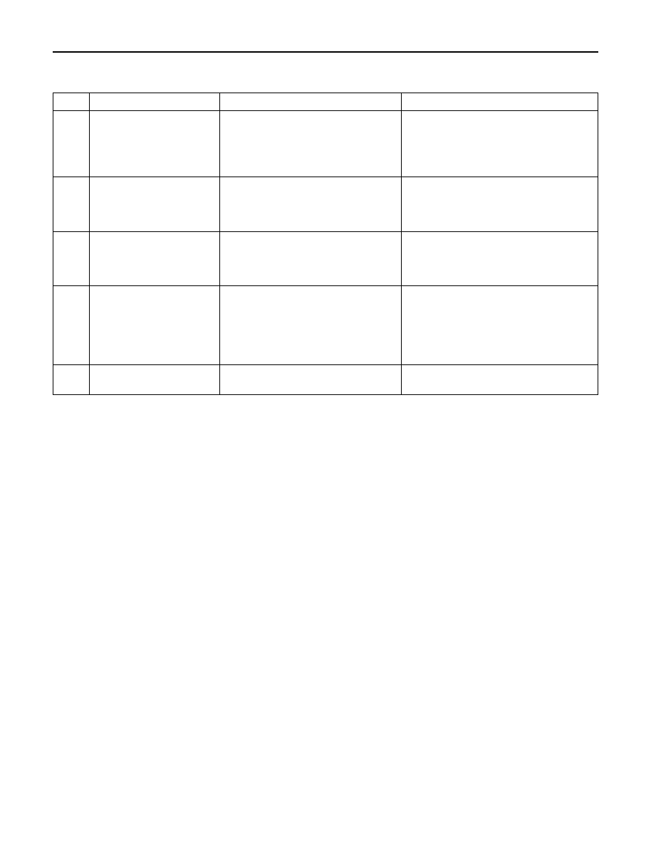
FAN CONTROL KNOB (FAN SWITCH) AND A/C
SWITCH
INDIVIDUAL INSPECTION
Check for continuity between fan switch and A/C switch
side connector terminals.
2
6 5 4 3
1
3
6
2
5
1
4
<Connector terminal>
I-23
I-18
I-23
I-18
5
A/C SW.
BEZEL
ILLUMI-
NATION
FAN SW.
OFF
1
2
3
4
3 2 6 1
2
5 3 6 4 1
HEATER & A/C, THERMOSTAT, COMPRESSOR,
CONDENSER FAN AND CERAMIC HEATER RELAY
Check for continuity between the relay terminals.
2 – 4 . . No continuity
(When battery voltage is applied between 1 – 3)
2 – 4 . . Continuity
2
2
1
1
4
4
3
3
Terminal
No.
SW.
position
DUAL PRESSURE SWITCH
2
1
Disconnect pressure switch connector and check for
continuity between pressure switch side connector
terminals.
00 – 42 SERVICE INFORMATION
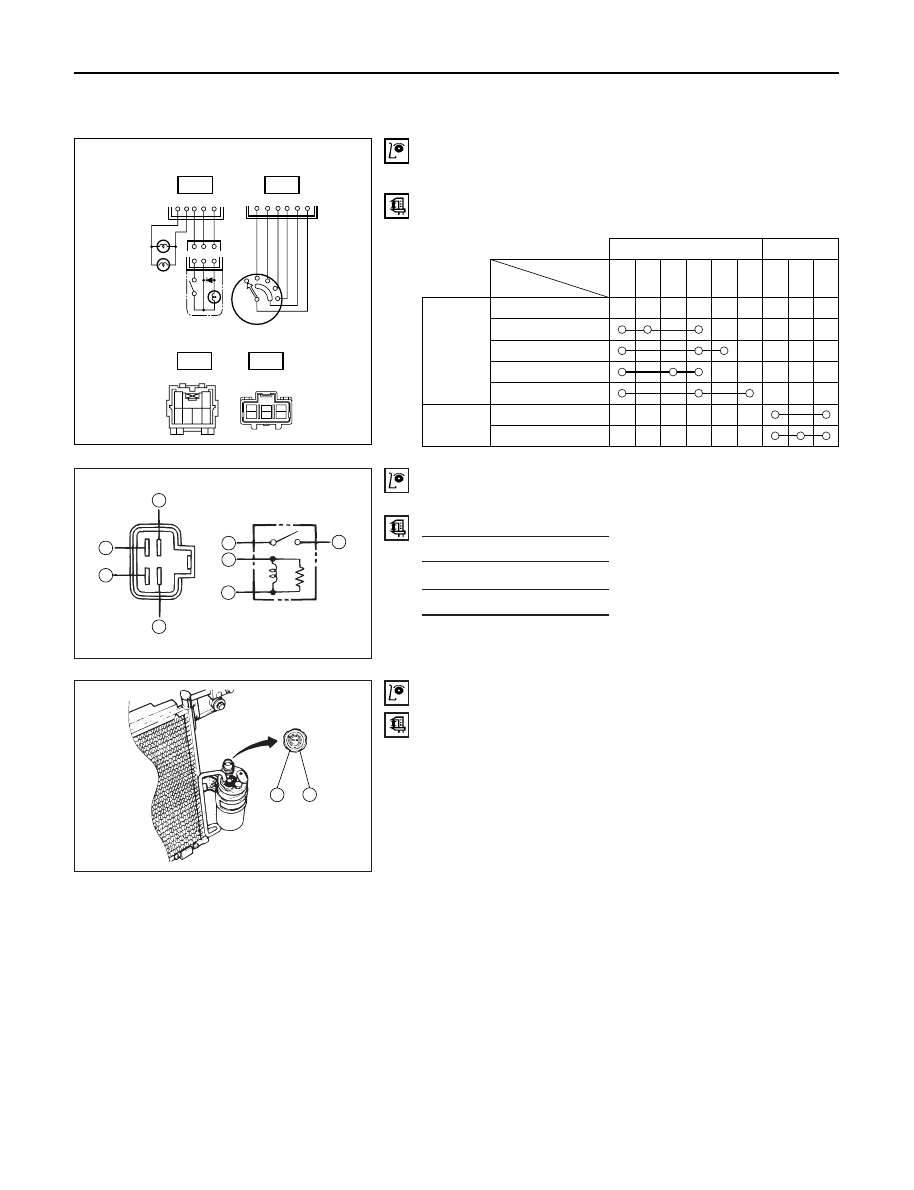
TRIPLE PRESSURE SWITCH (W/CONDENSER FAN)
4
3
1
2
1) Disconnect the connector and check for continuity
between pressure switch side connector terminal.
2) Reconnect the connector to activate the A/C switch,
and check to see if there is continuity between the
chassis side connectors and the fan operates.
[A/C OFF]
[A/C ON]
Terminal No.
Control
Continuity
1 - 2
Magnetic Clutch
Continuity
3 - 4
Condenser Fan
No Continuity
Terminal
Refrigerant Pressure
Continuity Fan
No.
1079
±
98 kPa
No
OFF
(11.0±1.0 kg·cm
2
/ 156±14 psi)
Continuity
3 - 4
1471±98 kPa
Continuity ON
(15.0±1.0 kg·cm
2
/ 213±14 psi)
BLOWER MOTOR
1
2
1) Disconnect the blower motor (B-5) connector from
the blower motor.
2) Connect the battery positive terminal to the No. 1
(NO.2; RHD) terminal of the blower motor and
negative to the No. 2 (NO. 1; RHD).
3) Be sure to check to see if the blower motor operates
correctly.
Terminal
Normal
SW.
No.
1
2
3
4
6
Operating
position
Resistance
2.4
Ω
0.90
Ω
0.28
Ω
–
1
2
3
4
RESISTOR
1
4
2
6
3
2
Motor
3
6
4
1
4
3
2
(SW.position)
(Connector
terminal)
1
1) Disconnect resistor (I-41) connector.
2) Check for continuity and resistance between the
terminals of the resistor.
SERVICE INFORMATION 00 – 43
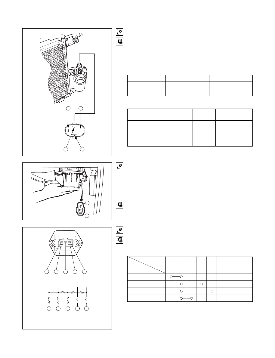
CONDENSER FAN
1
2
THERMO SWITCH (ENGINE)
1
2
1) Disconnect the condenser fan connector (C-75).
2) Connect the battery positive terminal to the No. 1
terminal and negative to No. 2.
3) Be sure to check to see if condenser fan operates
correctly.
With the environmental temperature of the switch set to
the following conditions, check to see if there is any
continuity between the switch side connector terminals.
Ambient
Terminal
Continuity
Temperature
No.
Above 77 – 83
°
C
1 – 2
No Continuity
(170.6–181.4
°
F)
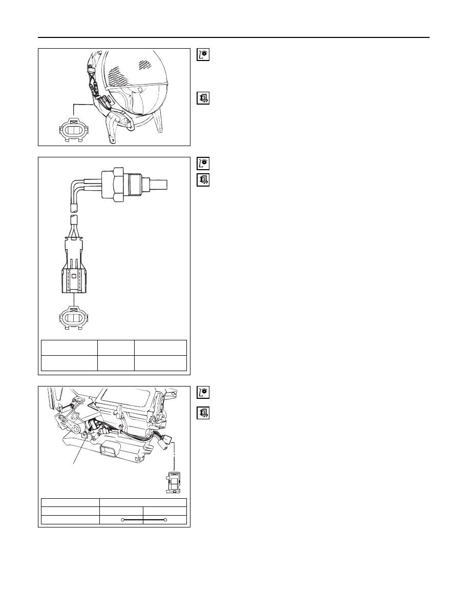
CERAMIC HEATER
1
2
Ceramic heater
Disconnect the ceramic heater connector and check for
continuity between ceramic heater side connector
terminals.
Connector No.
B-48
Terminal
1
2
Continuity
Нет комментариевНе стесняйтесь поделиться с нами вашим ценным мнением.
Текст