Opel Frontera UBS. Service manual — part 2088
6A–86
ENGINE MECHANICAL
11. Remove rear oil seal retainer assembly.
12. Remove main bearing cap.
13. Remove crankshaft.
14. Remove cylinder block.
Inspection and Repair
1. Remove the cylinder head gasket and any other
material adhering to the upper surface of the cylinder
block. Be very careful not to allow any material to
accidentally drop into the cylinder block. Be very
careful not to scratch the cylinder block.
2. Carefully remove the oil pump, rear oil seal retainer,
and crankcase assembly installation surface seal.
3. Wipe the cylinder block clean.
4. Visually inspect the cylinder block. If necessary, use a
flaw detector to perform a dye penetrate and
hydraulic (or air pressure) test. If cracking or other
damage is discovered, the cylinder block must either
be repaired or replaced.
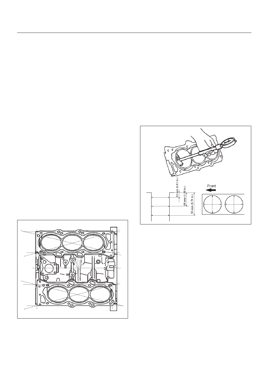
Flatness
1. Using a straight–edge and feeler gauge, check that
the upper surface of the cylinder block is not warped.
CAUTION: Be very careful not to allow any material
to accidentally drop into the upper surface of the
cylinder block. Be very careful not to scratch the
upper surface of the cylinder block.
2. The cylinder block must be reground or replaced if the
warpage exceeds the limit.
Warpage
Limit : 0.15 mm (0.0059 in)
Maximum repairable limit: 0.15 mm (0.0059 in)
012RS004
Cylinder Bore
Use a cylinder gauge to measure the cylinder bore
diameter in both the axial and thrust directions. Each
measurement should be made at six points.
CAUTION: Be very careful not to allow any material
to accidentally drop into the upper surface of the
cylinder block. Be very careful not to scratch the
upper surface of the cylinder block.
Cylinder Bore Inside Diameter
Limit : 93.530 (3.6823)
If the measurement exceed the specified limit, the
cylinder block must be replaced.
Diameter
Grade A : 93.400 mm–93.410 mm
(3.6772 in–3.6776 in)
Grade B : 93.411 mm–93.420 mm
(3.6776 in–3.6779 in)
Grade C : 93.421 mm–93.430 mm
(3.6780 in–3.6783 in)
012RS005
NOTE: For information on piston diameter, please refer
to the section ”Inspection of the Piston and Connecting
Rod Assembly” in this manual.
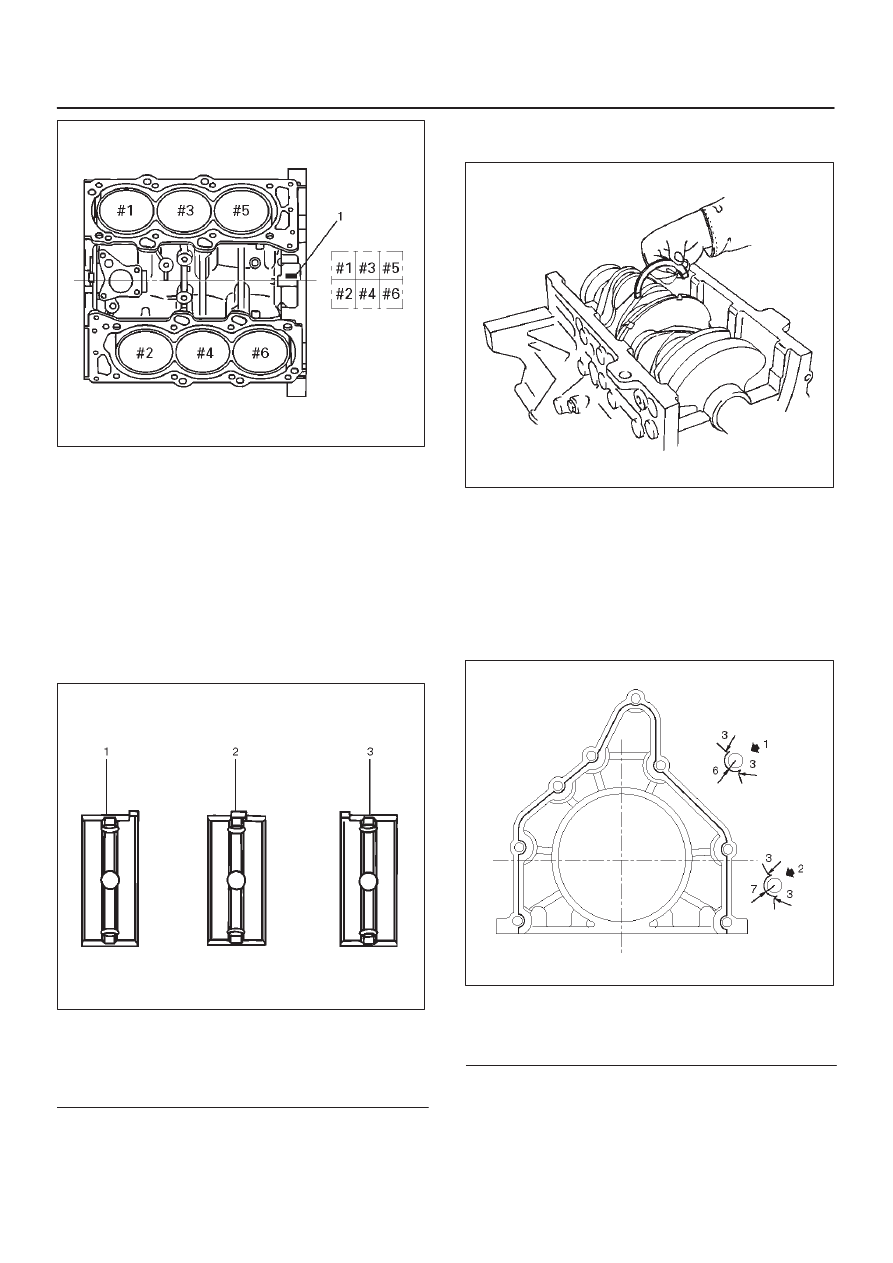
D
The ”Grade” mark (1) is stamped at the position
illustrated.
6A–87
ENGINE MECHANICAL
012RS006
Reassembly
1. Install cylinder block.
2. Install crankshaft.
D
Install the main bearings to the cylinder block and
the main bearing caps.
D
Be sure that they are positioned correctly.
D
Apply new engine oil to the upper and lower main
bearing faces.
NOTE: Do not apply engine oil to the bearing back faces.
015RS012
Legend
(1) Number 1 and 4 main bearing upper and lower.
(2) Number 2 and 3 main bearing upper.
(3) Number 2 and 3 main bearing lower.
D
Carefully mount the crankshaft.
D
Apply engine oil to the thrust washer.
D
Assemble the thrust washer to the No. 3 bearing
journal. The oil grooves must face the crankshaft.
015RS013
3. Install rear oil seal retainer.
D
Remove oil on cylinder block and retainer fitting
surface.
D
Apply sealant (TB1207B or equivalent) to retainer
fitting surface as shown in illustration.
D
The oil seal retainer must be installed within 5
minutes after sealant application before the sealant
hardens.
015RW002
Legend
(1) Around Bolt Holes
(2) Around Dowel Pin
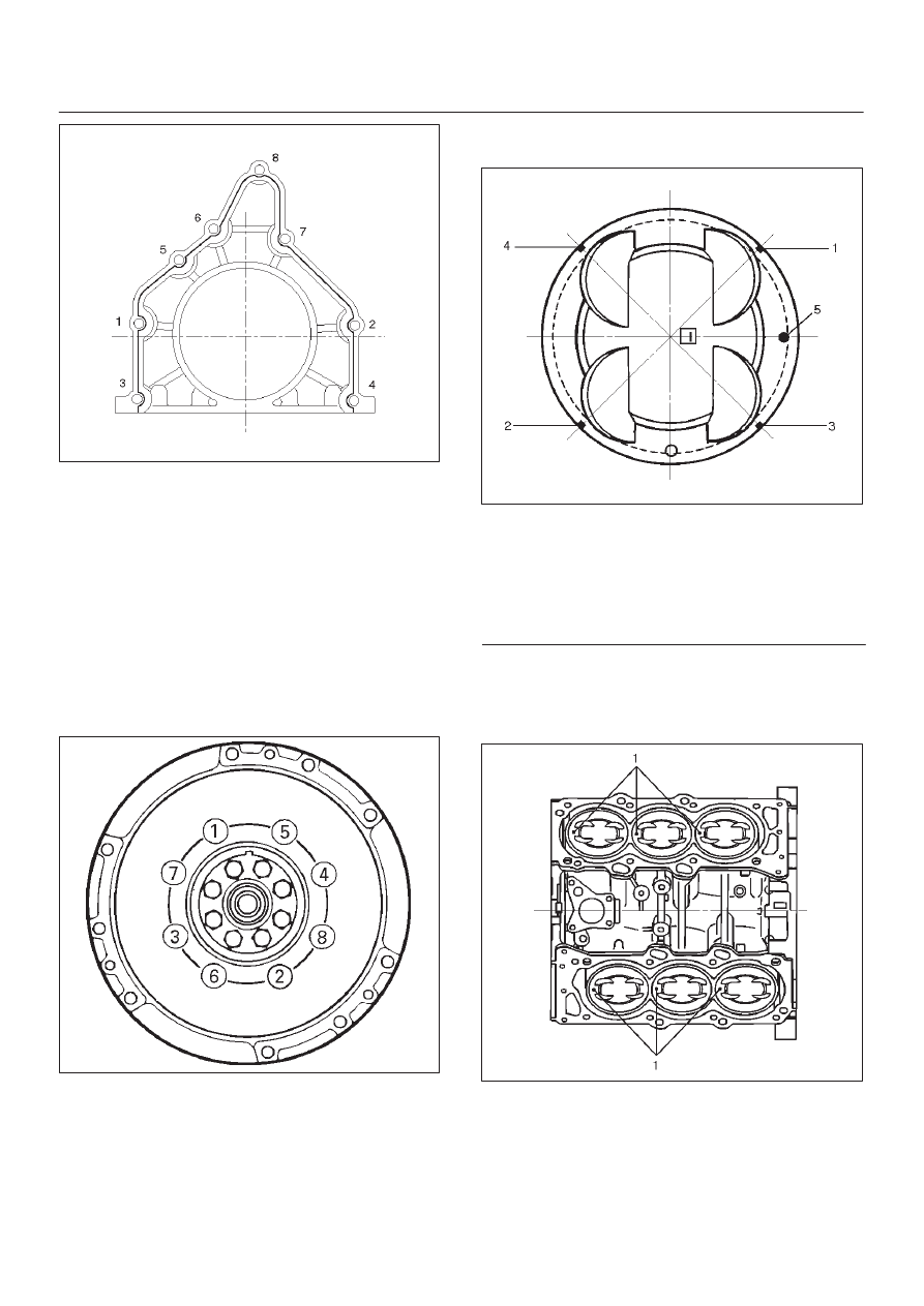
D
Apply engine oil to oil seal lip and align a dowel pin
hole in the cylinder block with that in the retainer.
D
Tighten retainer fixing bolts to the specified torque.
Torque: 25 N·m (2.5 Kg·m/18.4 lb ft)
6A–88
ENGINE MECHANICAL
015RW001
4. Install flywheel
1. Thoroughly clean and remove the oil from the
threads of crankshaft.
2. Remove the oil from the crankshaft and flywheel
mounting faces.
3. Mount the flywheel on the crankshaft and then
install the washer.
4. Holding the crankshaft stationary, tighten the
flywheel bolts in the order shown.
Torque: 54 N·m (5.5 Kg·m/40 lb ft)
NOTE: Do not reuse the bolts and do not apply oil or
thread lock to the bolts.
015RS018
5. Install piston and connecting rod assembly.
D
Apply engine oil to the cylinder bores, the
connecting rod bearings and the crankshaft pins.
NOTE: Do not apply engine oil to the bearing back faces.
D
Check to see that the piston ring end gaps are
correctly positioned.
015RS019
Legend
(1) No.1 Compression Ring
(2) No.2 Compression Ring
(3) Oil Ring Side Rail Upper
(4) Oil Ring Side Rail Lower
(5) Piston Front Mark
D
Insert the piston/connecting rod assemblies into
each cylinder with the piston ring compressor.
D
The front marks (1) must be facing the front of the
engine.
015RS020
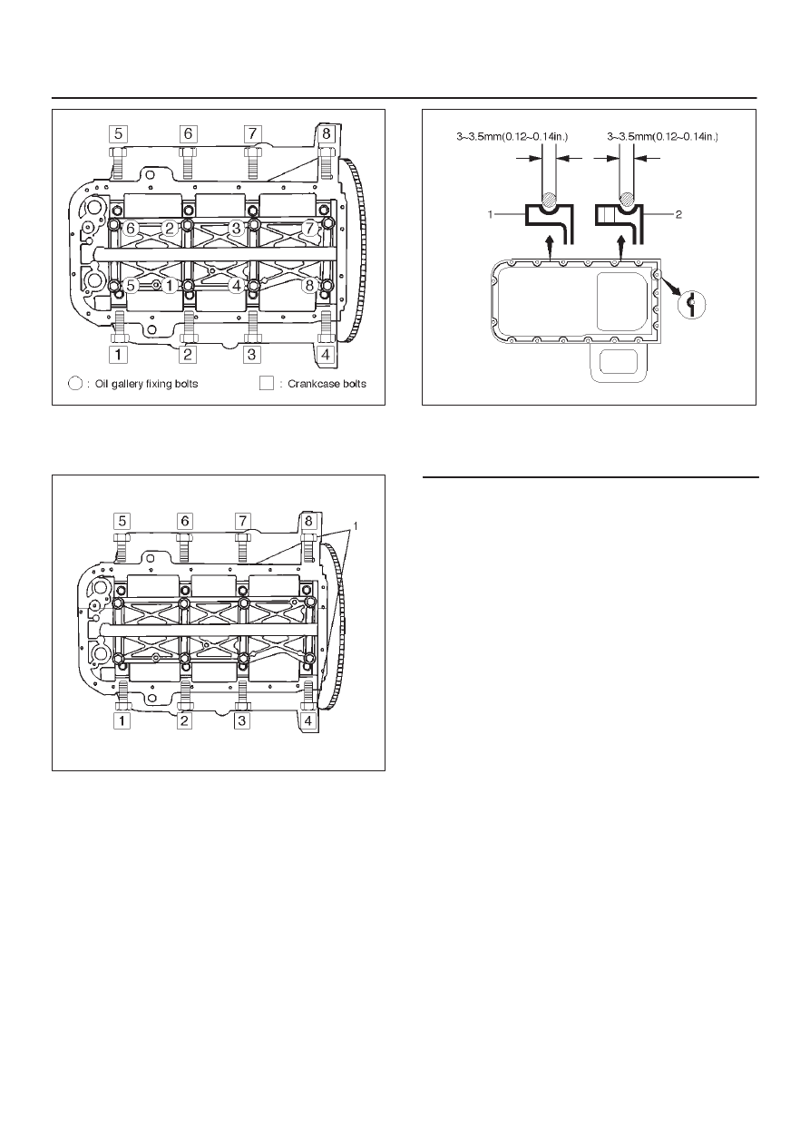
6. Install oil gallery and tighten the bolts in 2 steps in the
order shown.
1st step : 29 N·m (3.0 Kg·m/22 lb ft)
2nd step : 55
°
∼
65
°
6A–89
ENGINE MECHANICAL
012RS007
7. Install cylinder block side bolts (1) and tighten
crankcase bolts in sequence shown in the illustration.
Torque : 39 N·m (4.0 Kg·m/29 lb ft)
012RW005
8. Install oil pump assembly. Refer to “Oil Pump” in this
manual.
9. Install oil strainer and O-ring.
10. Install oil pipe and O-ring.
11. Install crankcase with oil pan.
1. Completely remove all residual sealant, lubricant
and moisture from the sealing surfaces. The
surfaces must be perfectly dry.
2. Apply a correct width bead of sealant (TB– 1207C
or its equivalent) to the contact surfaces of the
crankcase. There must be no gaps in the bead.
3. The oil pan must be installed within 5 minutes
after sealant application to prevent premature
hardening of sealant.
4. Tighten the bolts and nuts to the specified torque.
Torque : 10 N·m (1.0 Kg·m/89 lb in)
013RW010
Legend
(1) Portion Between Both Holes
(2) Bolt Hole Portions
12. Install cylinder head gasket.
13. Install cylinder head assembly. Refer to “Cylinder
Head” in this manual.
Нет комментариевНе стесняйтесь поделиться с нами вашим ценным мнением.
Текст