Opel Frontera UBS. Service manual — part 1744
8F–47
BODY STRUCTURE
Removal
CAUTION: For precautions on installation or
removal of SRS—air bag system, refer to
Supplemental Restraint System (SRS) — AIR BAG in
Restraint section.
1. Disconnect the battery ground cable.
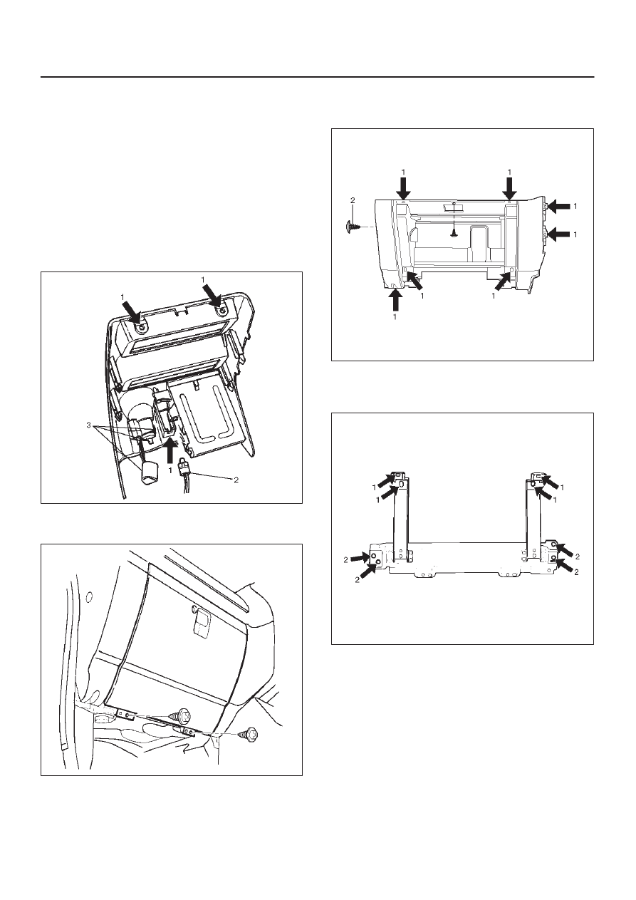
2. Remove front console assembly.
D
Remove the 4 fixing screws and disconnect the
switch connectors.
3. Remove lower cluster assembly.
D
Remove the 3 fixing screws (1) in order to
disconnect the cigarette lighter (3) and the
illumination (2) connectors.
740RS014
4. Remove glove box.
D
Remove the 2 fixing screws.
740RW104
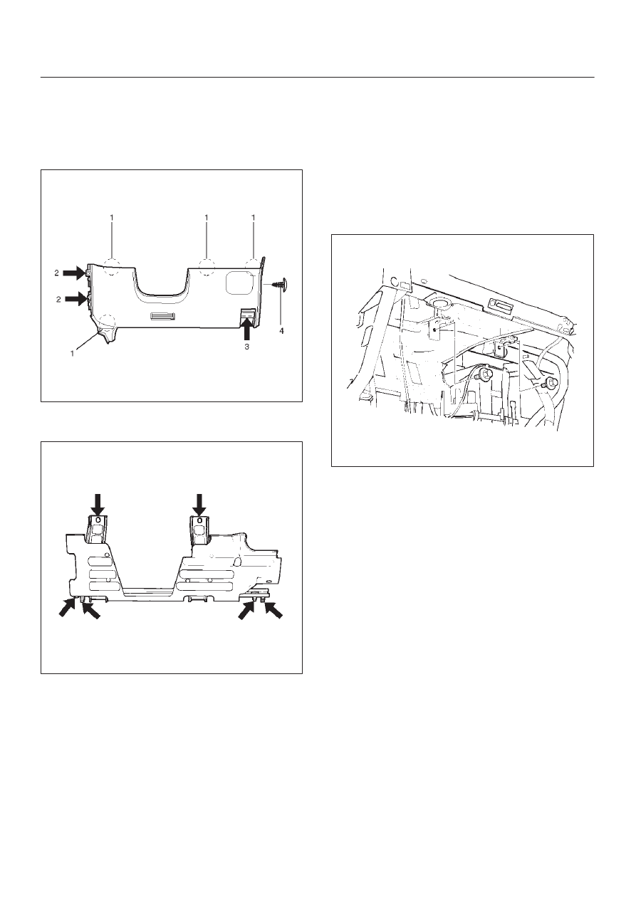
5. Remove instrument panel passenger lower cover
assembly.
D
Remove the 7 fixing screws (1) and 1 clip (2).
740RW103
6. Remove passenger knee bolster reinforcement
assembly.
D
Remove the 4 fixing bolts (2) and 4 nuts (1).
740RS011
8F–48
BODY STRUCTURE
7. Remove instrument panel driver lower cover
assembly.
D
Remove the engine hood opener fixing screws.
D
Remove the 2 fixing screws (2), 1 fixing bolt (3), and
1 clip (4). Pull out the fasteners at the 4 positions
(1).
740RW105
8. Remove driver knee bolster assembly (W/SRS).
D
Remove the 6 fixing nuts.
740RW122
9. Remove front defroster grille.
D
Pry 8 claws on the front side toward you side (room
side) and raise the grille upward.
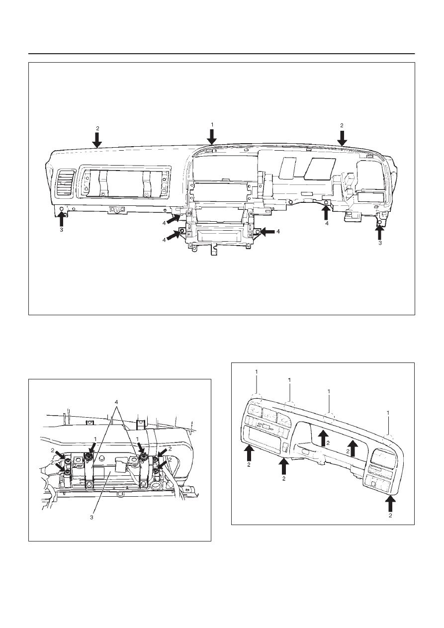
10. Remove instrument panel assembly.
D
Remove the 2 fixing bolts on the SRS adjust bracket
and the cross beam under the passenger inflator
module (W/SRS).
CAUTION: For precautions on installation or
removal of SRS — air bag system, refer to
Supplemental RestraintSystem (SRS) — AIR BAG in
Restraint section.
827RW031
D
Disconnect the 3 air conditioner control cables on
the unit side.
D
Remove the instrument harness connectors (5
connectors on the drivers side and 3 connectors on
the passenger side), the passenger inflator module
connector, the radio antenna cable plug, and the
ground cable fixing bolt on the center bracket.
D
Remove the 4 bolts (4) and the 2 nuts (3) under the
instrument panel assembly, and the upper left and
the upper right bolts (2) and the center nut (1).
8F–49
BODY STRUCTURE
740RW106
11. Remove passenger inflator module (W/SRS).
D
From the back of the instrument panel, remove the
4 fixing nuts (2) on the passenger inflator module (3)
and the 2 fixing nuts (1) and washers on the support
bracket (4), then disengage the 2 clips in order to
remove the passenger inflator module.
827RW032
12. Remove instrument panel cluster assembly.
D
Remove the 5 fixing screws (2) and pull the main
unit toward you and remove the clips at the 4
positions (1). Disconnect the switch connectors.
740RW107
8F–50
BODY STRUCTURE
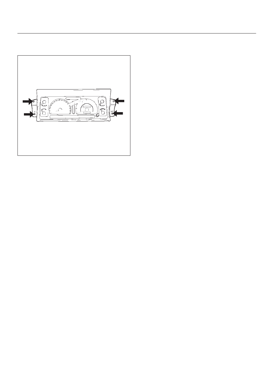
13. Remove meter assembly.
D
Remove the 4 meter assembly fixing screws and
disconnect the meter harness connectors.
821RS034
14. Remove control lever assembly.
D
Refer to Control Lever Assembly And/Or Control
Cables in Heating And Ventilation section.
15. Remove radio assembly.
D
Remove 2 fixing screws.
16. Remove vent duct assembly.
D
Remove 5 fixing screws.
17. Remove instrument harness assembly.
D
Remove the 4 fixing screws, fasteners at the 4
positions and the clips at the 7 positions.
18. Remove side defroster grille.
NOTE: For the order of removal steps in which each
items contained in the instrument panel assembly are
removed individually, refer to the chart.
Нет комментариевНе стесняйтесь поделиться с нами вашим ценным мнением.
Текст