Opel Zafira (2017 year). Instruction — part 13
198
Driving and operating
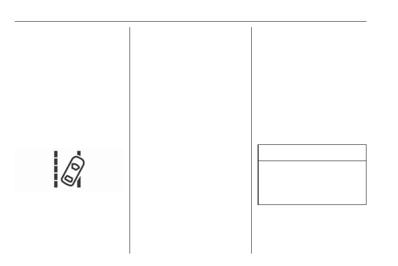
The lane departure warning system is
activated by pressing ). The
illuminated LED in the button
indicates that the system is switched
on. When the control indicator ) in
the instrument cluster illuminates
green, the system is ready to operate.
The system is only operable at
vehicle speeds above 56 km/h and if
lane markings are available.
When the system recognises an
unintended lane change, the control
indicator ) changes to yellow and
flashes. Simultaneously a chime
sound is activated.
Deactivation
The system is deactivated by
pressing ), the LED in the button
extinguishes.
At speeds below 56 km/h the system
is inoperable.
Fault
The lane departure warning system
may not operate properly when:
● The windscreen is not clean.
● There are adverse environmental
conditions like heavy rain, snow,
direct sunlight or shadows.
The system can not operate when no
lane marking is detected.
Fuel
Fuel for petrol engines
Only use unleaded fuel that complies
with European standard EN 228 or
E DIN 51626-1 or equivalent.
The engine is capable of running with
fuel that contains up to 10% ethanol
(e.g. named E10).
Use fuel with the recommended
octane rating. A lower octane rating
can reduce engine power and torque
and slightly increases fuel
consumption.
Caution
Do not use fuel or fuel additives
that contain metallic compounds
such as manganese-based
additives. This may cause engine
damage.
-------------------------------------------------------------------------------------------------------------------------------------------------------------
Driving and operating
199
Caution
Use of fuel that does not comply to
EN 228 or E DIN 51626-1 or
equivalent can lead to deposits or
engine damage.
Caution
Use of fuel with a lower octane
rating than the lowest possible
rating could lead to uncontrolled
combustion and engine damage.
The engine specific requirements
regarding octane rating are given in
the engine data overview 3 267. A
country specific label at the fuel filler
flap can supersede the requirement.
Fuel for diesel engines
Only use diesel fuel that complies
with EN 590.
In countries outside the European
Union use Euro-Diesel fuel with a
sulphur concentration below 50 ppm.
Caution
Use of fuel that does not comply to
EN 590 or similar can lead to
engine powerloss, increased wear
or engine damage and may affect
your warranty.
Do not use marine diesel oils, heating
oils, Aquazole and similar diesel-
water emulsions. Diesel fuels must
not be diluted with fuels for petrol
engines.
Fuel for natural gas
operation
Use natural gas with a methane
content of approx. 78 - 99%. L-gas
(low) has approx. 78 - 87% and H-gas
(high) has approx. 87 - 99%. Biogas
with the same methane content can
also be used if it has been chemically
prepared and desulphurised.
Only use natural gas or biogas that
complies with DIN 51624.
Liquid gas or LPG must not be used.
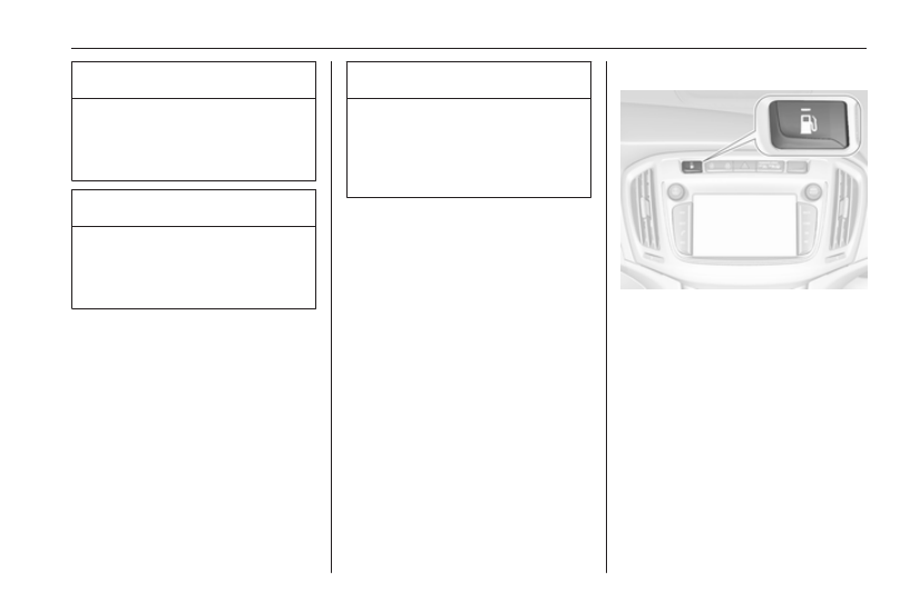
Fuel selector
Pressing Y switches between petrol
and natural gas operation. Switching
is not possible at high loads (e.g.
powerful acceleration, driving at full
throttle). The LED status shows the
current operating mode.
1
off
: natural gas
operation
1
illumi‐
nates
: petrol operation
1
flashes
: no switching is
possible, one type of
fuel is empty
-------------------------------------------------------------------------------------------------------------------------------------------------------------
200
Driving and operating
As soon as the natural gas tank is
empty, petrol operation is
automatically engaged until the
ignition is switched off.
If the natural gas tank is not refuelled,
the system must be instructionly
switched to petrol operation before
the engine is restarted. This will
prevent damage to the catalytic
converter (overheating caused by
irregular fuel supply).
If the selector switch is operated
several times within a short time, a
switchover inhibitor is activated. The
engine remains in the current
operating mode. The inhibitor
remains active until the ignition is
switched off.
A slight loss of power and torque can
be expected during petrol operation.
You must therefore adapt your driving
style (e.g. during overtaking
manoeuvres) and high vehicle loads
(e.g. towing loads) accordingly.
Every six months run the petrol tank
down until control indicator Y
illuminates, then refuel. This is
necessary to maintain fuel quality as
well as system function necessary for
petrol operation.
Fill the tank completely at regular
intervals to prevent corrosion in the
tank.
Fuel for liquid gas operation
Liquid gas is known as LPG
(Liquefied Petroleum Gas) or under
its French name GPL (Gaz de Pétrole
Liquéfié). LPG is also known as
Autogas.
LPG consists mainly of propane and
butane. The octane rating is between
105 and 115, depending on the
butane proportion. LPG is stored as a
liquid at a pressure of approximately
five to ten bar.
The boiling point depends on the
pressure and the mixing ratio. At
ambient pressure, it is between
-42 °C (pure propane) and -0.5 °C
(pure butane).
Caution
The system works at an ambient
temperature of approx. -8 °C to
100 °C.
Full functioning of the LPG system
can only be guaranteed with liquid
gas which complies with the minimum
requirements of DIN EN 589.
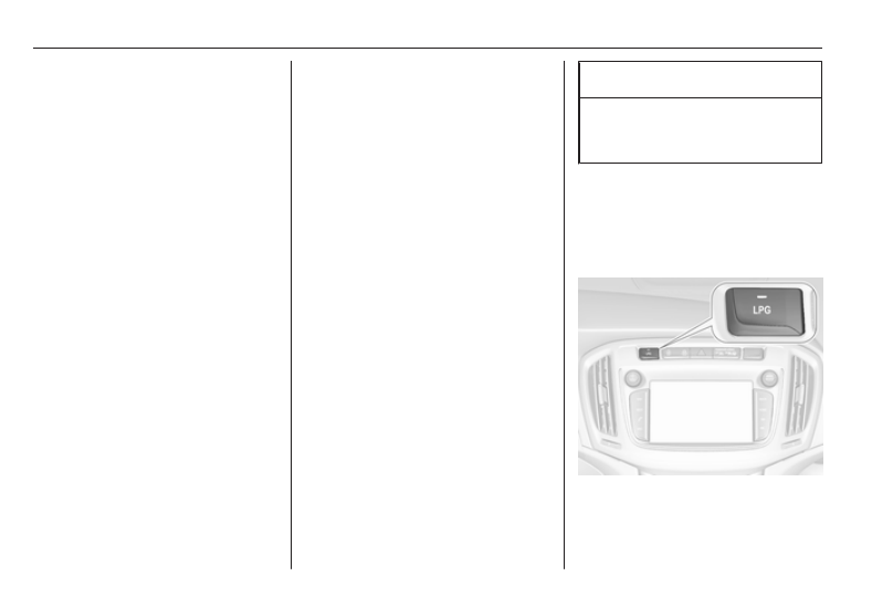
Fuel selector
Pressing LPG switches between
petrol and liquid gas operation as
soon as the required parameters
(coolant temperature, gas
-------------------------------------------------------------------------------------------------------------------------------------------------------------
Driving and operating
201
temperature and minimum engine
speed) have been reached. The
requirements are usually fulfilled after
approximately 60 seconds
(depending on exterior temperature)
and the first firm press on the
accelerator. The status LED shows
the current operating mode.
1
off
: petrol operation
1
flashes : checking conditions
for fuel transition to
liquid gas operation.
Illuminates if
conditions are fulfilled.
1
illumi‐
nates
: liquid gas operation
1
flashes 5
times and
extin‐
guishes
: liquid gas tank is
empty or failure in
liquid gas system. A
message is displayed
in the Driver
Information Centre.
If the fuel tank is empty, the engine
will not start.
The selected fuel mode is stored and
reactivated at the next ignition cycle if
conditions allow.
As soon as the liquid gas tank is
empty, petrol operation is
automatically engaged until the
ignition is switched off.
When switching automatically
between petrol or gas operation, a
brief delay of engine tractive power
may be noticeable.
Every six months, run the petrol tank
down until control indicator I
illuminates, then refuel. This helps
maintain fuel quality and system
function for petrol operation.
Fill the tank completely at regular
intervals to prevent corrosion in the
tank.
Faults and remedies
If gas mode is not possible, check the
following:
● Is there enough liquid gas
present?
● Is there enough petrol present for
starting?
Due to extreme temperatures in
combination with the gas
composition, it may take slightly
longer before the system switches
from petrol to gas mode.
In extreme situations, the system may
also switch back to petrol mode if the
minimum requirements are not
fulfilled. If conditions allow, it may be
possible to instructionly switch back to
liquid gas operation.
Seek the assistance of a workshop in
the event of all other faults.
Caution
Repairs and adjustments may only
be made by trained specialists in
order to maintain the safety and
warranty on the LPG system.
Liquid gas is given a particular odour
(odorised) so that any leaks can be
detected easily.
-------------------------------------------------------------------------------------------------------------------------------------------------------------
202
Driving and operating
9 Warning
If you smell gas in the vehicle or in
the immediate vicinity, switch to
petrol mode immediately. No
smoking. No naked flames or
ignition sources.
If the gas odour persists, do not start
the engine. Have the cause of the
fault remedied by a workshop.
When using underground car parks,
follow the instructions of the operator
and local laws.
Note
In the event of an accident, switch off
the ignition and lights.
Refuelling
9 Danger
Before refuelling, switch off
ignition and any external heaters
with combustion chambers.
Switch off any mobile phones.
Follow the operating and safety
instructions of the filling station
when refuelling.
9 Danger
Fuel is flammable and explosive.
No smoking. No naked flames or
sparks.
If you can smell fuel in your
vehicle, have the cause of this
remedied immediately by a
workshop.
Caution
In case of misfuelling, do not
switch on ignition.
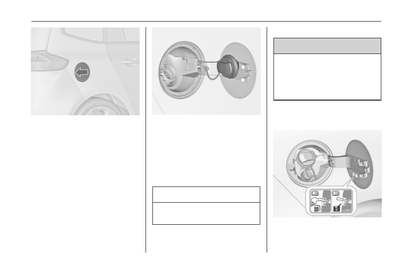
Fuel filler flap is located at right rear
side of the vehicle.
-------------------------------------------------------------------------------------------------------------------------------------------------------------
Driving and operating
203
The fuel filler flap can only be opened
if the vehicle is unlocked. Release the
fuel filler flap by pushing the flap.
Petrol and Diesel refuelling
To open, turn the cap slowly
anticlockwise.
The fuel filler cap can be retained in
the bracket on the fuel filler flap.
To refuel, fully insert the pump nozzle
and switch it on.
After the automatic cut-off, the tank
can be topped up by operating the
pump nozzle a maximum of two more
times.
Caution
Wipe off any overflowing fuel
immediately.
To close, turn the fuel filler cap
clockwise until it clicks.
Close the flap and allow it to engage.
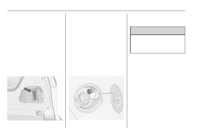
Vehicles with misfuel inhibitor
9 Warning
Do not try to open the flap of the
fuel filler neck instructionly on
vehicles with misfuel inhibitor.
Disregarding this could lead to
trapping of the fingers.
Vehicles with a selective catalytic
reduction system are equipped with a
misfuel inhibitor.
-------------------------------------------------------------------------------------------------------------------------------------------------------------
204
Driving and operating
The misfuel inhibitor ensures that the
flap of the fuel filler neck can only be
opened by using a nozzle for diesel
fuel or a funnel for emergency
refilling.
Turn the fuel filler cap slowly
anticlockwise.
The cap can be retained in the
bracket on the fuel filler flap.
Place the nozzle in a straight line to
the filler neck and press with slight
force to insert.
In case of an emergency, refill with a
canister. A funnel must be used to
open the cap of the filler neck.
The funnel is located on the right-
hand side storage compartment in the
load compartment.
Place the funnel in a straight line to
the filler neck and press with slight
force to insert.
Use the funnel to fill the diesel fuel into
the filler neck.
After topping-up, put the funnel into
the plastic bag and stow it in the
storage compartment.
Selective catalytic reduction system
Natural gas refuelling
The fuel filler flap can only be opened
if the vehicle is unlocked. Release the
fuel filler flap by pushing the flap.
9 Warning
Refuel only with a maximum
output pressure of 250 bar. Use
only temperature-compensated
filling stations.
The refuelling procedure must be
completed, i.e. the filler neck must be
vented.
The capacity of the natural gas tank
depends on outside temperature,
filling pressure and type of refuelling
system. Capacities 3 272.
Close the flap and allow it to engage.
Terms for "natural gas vehicles"
abroad:
-------------------------------------------------------------------------------------------------------------------------------------------------------------
Driving and operating
205
German Erdgasfahrzeuge
English NGVs = Natural Gas Vehi‐
cles
French Véhicules au gaz naturel -
or - Véhicules GNV
Italian
Metano auto
Terms for "natural gas" abroad:
German Erdgas
English CNG = Compressed
Natural Gas
French GNV = Gaz Naturel (pour)
Véhicules - or -
CGN = carburantgaz
naturel
Italian
Metano (per auto)
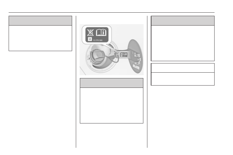
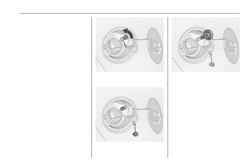
Liquid gas refuelling
Follow the operating and safety
instructions of the filling station when
refuelling.
The filling valve for the liquid gas is
behind the fuel filler cap.
Unscrew protective cap from the filler
neck.
Screw the required adapter hand-
tight onto the filler neck.
ACME Adapter: Screw the nut of the
filling nozzle onto the adapter. Press
locking lever on filler nozzle down.
DISH filler neck: Place the filler nozzle
into the adapter. Press locking lever
on filler nozzle down.
Bayonet filler neck: Place filler nozzle
on the adapter and turn clockwise or
anticlockwise through one quarter
turn. Pull locking lever of filler nozzle
fully.
EURO filler neck: Press the filler
nozzle onto the adapter until it
engages.
-------------------------------------------------------------------------------------------------------------------------------------------------------------
206
Driving and operating
Press the button at the liquid gas
supply point. The filling system stops
or begins to run slowly when 80% of
the tank volume is reached
(maximum fill level).
Release button on filling system to
stop the filling process. Release the
locking lever and remove the filler
nozzle. A small quantity of liquid gas
may escape.
Remove adapter and stow in vehicle.
Fit protective cap to prevent the
penetration of foreign bodies into the
filler opening and the system.
9 Warning
Due to the system design, an
escape of liquid gas after
releasing the locking lever is
unavoidable. Avoid inhaling.
9 Warning
The liquid gas tank should only be
filled to 80% capacity, for safety
reasons.
The multivalve on the liquid gas tank
automatically limits the fill quantity. If
a larger quantity is added, we
recommend not exposing the vehicle
to the sun until the excess amount
has been used up.
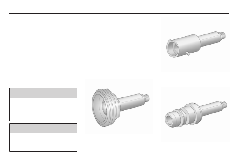
Filling adapter
As filling systems are not
standardised, different adapters are
required which are available from
Opel Distributors and from Opel
Authorised Repairers.
ACME adapter: Belgium, Germany,
Ireland, Luxembourg, Switzerland
Bayonet adapter: Netherlands,
Norway, Spain, United Kingdom
EURO adapter: Spain
-------------------------------------------------------------------------------------------------------------------------------------------------------------
Driving and operating
207
DISH adapter: Austria, Bosnia-
Herzegovina, Bulgaria, Croatia,
Czech Republic, Denmark, Estonia,
France, Greece, Hungary, Italy,
Latvia, Lithuania, Macedonia,
Poland, Portugal, Romania, Serbia,
Slovakia, Slovenia, Sweden,
Switzerland, Turkey, Ukraine,
Fuel filler cap
Only use genuine fuel filler caps.
Diesel-engined vehicles have special
fuel filler caps.
Fuel consumption - CO
2
-
Emissions
Petrol and Diesel engines
The fuel consumption (combined) of
the model Opel Zafira is within a
range of 9.2 to 4.9 l/100 km.
The CO
2
emission (combined) is
within a range of 182 to 129 g/km.
For the values specific to your
vehicle, refer to the EEC Certificate of
Conformity provided with your vehicle
or other national registration
documents.
Natural gas engines
The gas consumption (combined) of
the model Opel Zafira is
4.7 kg/100 km.
The CO
2
emission (combined) is
129 g/km.
For the values specific to your
vehicle, refer to the EEC Certificate of
Conformity provided with your vehicle
or other national registration
documents.
General information
The official fuel consumption and
specific CO
2
emission figures quoted
relate to the EU base model with
standard equipment.
Fuel consumption data and CO
2
emission data are determined
according to regulation
R (EC) No. 715/2007 (in the version
respectively applicable), taking into
consideration the vehicle weight in
running order, as specified by the
regulation.
The figures are provided only for the
purpose of comparison between
different vehicle variants and must
not be taken as a guarantee for the
actual fuel consumption of a
particular vehicle. Additional
equipment may result in slightly
higher results than the stated
consumption and CO
2
figures.
Furthermore, fuel consumption is
dependent on personal driving style
as well as road and traffic conditions.
-------------------------------------------------------------------------------------------------------------------------------------------------------------
208
Driving and operating
Natural gas
The fuel consumption information
was obtained using reference fuel
G20 (methane proportion
99 - 100 mol%) under prescribed
driving conditions. When using
natural gas with a lower proportion of
methane, the fuel consumption can
differ from the specified values.
Trailer hitch
General information
Only use towing equipment that has
been approved for your vehicle.
Vehicles with natural gas engines
require special towing equipment.
Entrust retrofitting of towing
equipment to a workshop. It may be
necessary to make changes that
affect the cooling system, heat
shields or other equipment.
The bulb outage detection function for
trailer brake light cannot detect a
partial bulb outage. E.g. in case of
4x 5 Watt bulbs, the function only
detects lamp outage when only a
single 5 Watt lamp remains or none
remain.
Fitting of towing equipment could
cover the opening of the towing eye.
If this is the case use the coupling ball
bar for towing. Always keep the
coupling ball bar in the vehicle.
Driving characteristics and
towing tips
Before attaching a trailer, lubricate
the coupling ball. However, do not do
so if a stabiliser, which acts on the
coupling ball, is being used to reduce
snaking movements.
For trailers with low driving stability
and caravan trailers with a permitted
gross vehicle weight of more than
1300 kg the use of a stabiliser is
strongly recommended when driving
above 80 km/h.
If the trailer starts snaking, drive more
slowly, do not attempt to correct the
steering and brake sharply if
necessary.
When driving downhill, drive in the
same gear as if driving uphill and
drive at a similar speed.
Adjust tyre pressure to the value
-------------------------------------------------------------------------------------------------------------------------------------------------------------
Driving and operating
209
Trailer towing
Trailer loads
The permissible trailer loads are
vehicle and engine-dependent
maximum values which must not be
exceeded. The actual trailer load is
the difference between the actual
gross weight of the trailer and the
actual coupling socket load with the
trailer coupled.
The permissible trailer loads are
specified in the vehicle documents. In
general, they are valid for gradients
up to 12%.
The permissible trailer load applies
up to the specified incline and at sea
level. Since engine power decreases
as altitude increases due to the air
becoming thinner, therefore reducing
climbing ability, the permissible gross
train weight also decreases by 10%
for every 1000 metres of altitude. The
gross train weight does not have to be
reduced when driving on roads with
slight inclines (less than 8%, e.g.
motorways).
The permissible gross train weight
must not be exceeded. This weight is
specified on the identification plate
Vertical coupling load
The vertical coupling load is the load
exerted by the trailer on the coupling
ball. It can be varied by changing the
weight distribution when loading the
trailer.
The maximum permissible vertical
coupling load (75 kg) is specified on
the towing equipment identification
plate and in the vehicle documents.
Note
Engines B20DTH and B20DTJ:
Depending on the equipment the
maximum permissible vertical
coupling load can be 75 kg or 60 kg.
Always aim for the maximum load,
especially in the case of heavy
trailers. The vertical coupling load
should never fall below 25 kg.
Rear axle load
When the trailer is coupled and the
towing vehicle fully loaded, the
permissible rear axle load (see
identification plate or vehicle
documents) may be exceeded by
60 kg, the gross vehicle weight rating
may be exceeded by 60 kg. If the
permissible rear axle load is
exceeded, a maximum speed of
100 km/h applies.
Towing equipment
Caution
When operating without a trailer,
remove the coupling ball bar.
-------------------------------------------------------------------------------------------------------------------------------------------------------------
210
Driving and operating
Stowage of coupling ball bar
The bag with the coupling ball bar is
stowed in the load compartment.
Place the strap through the right rear
lashing eye, wrap around twice and
tighten the strap to secure the bag.
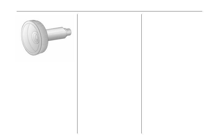
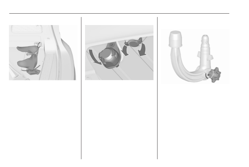
Fitting the coupling ball bar
Disengage and fold down the socket.
Remove the sealing plug from the
opening for the coupling ball bar and
stow it.
Checking the tensioning of the
coupling ball bar
● Red marking on rotary knob must
point towards green marking on
coupling ball bar.
● The gap between the rotary knob
and the coupling ball bar must be
approx. 6 mm.
● The key must be in position c.
Otherwise, the coupling ball bar must
be tensioned before being inserted:
● Unlock coupling ball bar by
turning key to position c.
-------------------------------------------------------------------------------------------------------------------------------------------------------------
Driving and operating
211
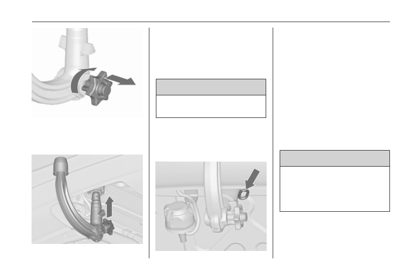
● Pull out rotary knob and turn
clockwise as far as it will go.
Inserting the coupling ball bar
Insert the tensioned coupling ball bar
in the opening and push firmly
upwards until it audibly engages.
The rotary handle snaps back into its
original position resting against the
coupling ball bar without a gap.
9 Warning
Do not touch rotary handle during
insertion.
Lock the coupling ball bar by turning
the key to position e. Remove the key
and close the protective flap.
Eye for break-away stopping cable
Attach breakaway stopping cable to
eye.
Check that the coupling ball bar is
correctly installed
● Green marking on rotary knob
must point towards green
marking on coupling ball bar.
● There must be no gap between
the rotary handle and the
coupling ball bar.
● The coupling ball bar must be
firmly engaged in the opening.
● The coupling ball bar must be
locked and the key removed.
9 Warning
Towing a trailer is permitted only
when a coupling ball bar is fitted
correctly. If the coupling ball bar
does not engage correctly, seek
the assistance of a workshop.
-------------------------------------------------------------------------------------------------------------------------------------------------------------
212
Driving and operating
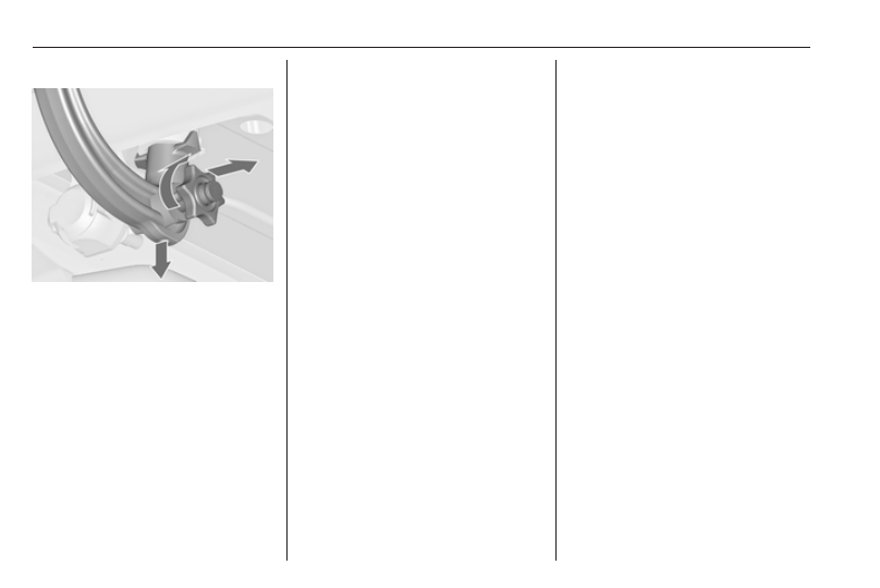
Dismounting the coupling ball bar
Open the protective flap and turn the
key to position c to unlock the
coupling ball bar.
Pull out rotary handle and turn
clockwise as far as it will go. Pull out
coupling ball bar downwards.
Insert sealing plug in opening. Fold
away socket.
Trailer stability assist
If the system detects snaking
movements, engine power is reduced
and the vehicle/trailer combination is
selectively braked until the snaking
ceases. While system is working keep
steering wheel as still as possible.
Trailer stability assist (TSA) is a
function of the Electronic Stability
Control 3 170.
-------------------------------------------------------------------------------------------------------------------------------------------------------------
Vehicle care
213
Vehicle care
General Information . . . . ... 214
Accessories and vehicle
modifications . . . . . . .. 214
Vehicle storage . . . . . . 214
End-of-life vehicle recovery . . 215
Vehicle checks . . . . . . ... 215
Performing work . . . . . .. 215
Bonnet . . . . . . . . . . 215
Engine oil . . . . . . . . . 216
Engine coolant . . . . . . . 217
Power steering fluid . . . . . 218
Washer fluid . . . . . . . 218
Brakes . . . . . . . . . . 219
Brake fluid . . . . . . . ... 219
Vehicle battery . . . . . . . 219
Diesel fuel system bleeding . . 221
Wiper blade replacement . . 221
Bulb replacement . . . . . ... 222
Halogen headlights . . . . .. 222
LED headlights . . . . . . 224
Fog lights . . . . . . . . . 224
Tail lights . . . . . . . . . 225
Side turn signal lights . . . .. 227
Number plate light . . . . ... 228
Interior lights . . . . . . . 228
Instrument panel illumination ... 229
Electrical system . . . . . . 229
Fuses . . . . . . . . . ... 229
Engine compartment fuse box . 230
Instrument panel fuse box . ... 232
Load compartment fuse box . 233
Vehicle tools . . . . . . . .. 235
Tools . . . . . . . . . . 235
Wheels and tyres . . . . . ... 236
Winter tyres . . . . . . . . 236
Tyre designations . . . . . 236
Tyre pressure . . . . . . .. 236
Tyre pressure monitoring
system . . . . . . . . . 238
Tread depth . . . . . . . . 241
Changing tyre and wheel size . 241
Wheel covers . . . . . . ... 241
Tyre chains . . . . . . . .. 242
Tyre repair kit . . . . . . .. 242
Wheel changing . . . . . ... 245
Spare wheel . . . . . . . 247
Jump starting . . . . . . . . 251
Towing . . . . . . . . . ... 252
Towing the vehicle . . . . ... 252
Towing another vehicle . . ... 253
Appearance care . . . . . ... 254
Exterior care . . . . . . . 254
Interior care . . . . . . . . 256
-------------------------------------------------------------------------------------------------------------------------------------------------------------
Нет комментариевНе стесняйтесь поделиться с нами вашим ценным мнением.
Текст