Isuzu Rodeo UE. Service manual — part 32
2A–24 POWER–ASSISTED STEERING SYSTEM
Inspection and Repair
Make all necessary adjustments, repairs, and part
replacements if wear, damage, or other problems are
discovered during inspection.
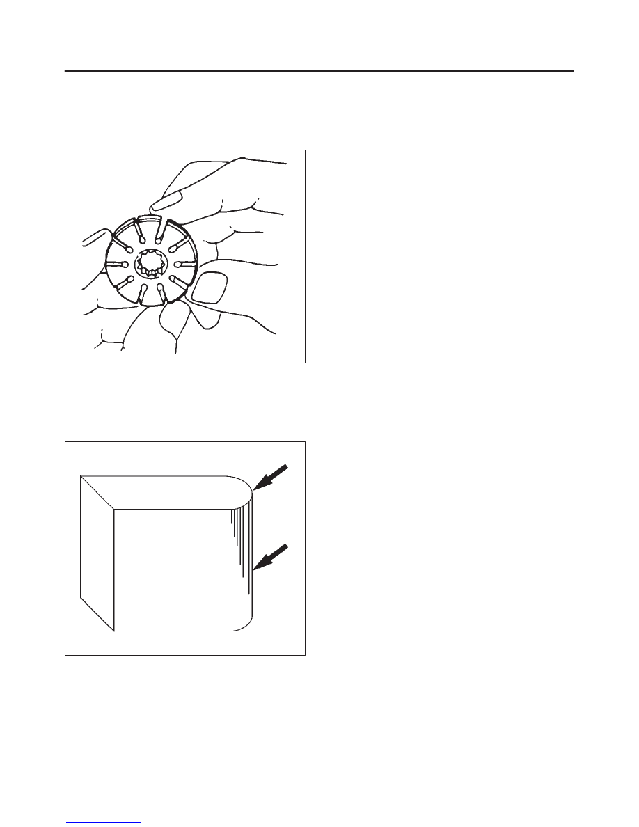
Rotor
442RS002
Check that the groove in the vane is free from excessive
wear and that the vane slides smoothly. When part
replacement becomes necessary, the pump cartridge
should be replaced as a subassembly.
Vane
442RS003
Sliding faces of the vane should be free from wear.
(Particularly the curved face at the tip that contact with the
cam should be free from wear and distortion). When part
replacement becomes necessary, the pump cartridge
should be replaced as a subassembly.
Cam
The inner face of the arm should have a uniform contact
pattern without a sign of step wear. When part
replacement becomes necessary, the pump cartridge
should be replaced as a subassembly.
Side Plate
The sliding faces of parts must be free from step wear
(more than 0.01 mm), which can be felt by the finger nail.
The parts with minor scores may be reused after lapping
the face.
Relief Valve
The sliding face of the valve must be free from burrs and
damage. The parts with minor scores may be reused after
smoothing with emery cloth (#800 or finer).
Shaft
Oil seal sliding faces must be free from a step wear which
can be felt by the finger nail. Bushing fitting face must be
free from damage and wear.
O-ring, Oil Seal, Snap Ring
Be sure to discard used parts, and always use new parts
for installation. Prior to installation, lubricate all seals and
rings with power steering fluid.
Pressure Switch
Check the switch operation as follows:
With engine idling and A/C on, turn the steering wheel
fully to the left; compressor should interrupt and engine
idle speed will increase. Shut off A/C and again turn
steering fully to the left; engine idle will increase. If system
fails to function properly, disconnect connector at the
pressure switch and repeat system check while testing
continuity across disconnected SW connector.
Reassembly
1. Install oil seal to front housing. Be sure to discard
used oil seal, and always use new parts for
installation.
CAUTION: When installing the oil seal, be careful
not to damage the oil seal contacting surface of the
housing.
2. Install shaft assembly.
POWER–ASSISTED STEERING SYSTEM
2A–25
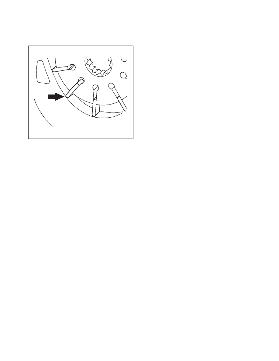
3. Install the vanes to roter with curved face in contact
with the inner wall of cam.
442RS005
4. Install roter and vanes to cam.
5. Install pin to front housing.
6. Install two new O-rings to front housing. Be sure to
discard used O-ring.
7. Install side plate.
CAUTION: When installing side plate, be careful not
to damage its inner surface. Damaged side plate may
cause poor pump performance, pump seizure or oil
leakage.
8. Install pump cartridge assembly to front housing.
9. Install snap ring to shaft end.
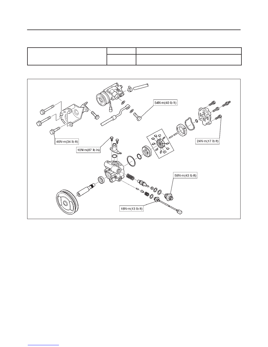
10. Install rear housing with a new O-ring. Be sure to
discard used O-ring. Then install bolt and tighten it to
specified torque.
Torque: 24 N·m (17 lb ft)
11. Install suction pipe with a new O-ring. Be sure to
discard used O-ring. Then install bolt and tighten it to
specified torque.
Torque: 10 N·m (87 lb in)
12. Install relief valve and spring.
13. Install connector with a new O-ring. Be sure to
discard used O-ring. Tighten the connector to
specified torque.
Torque: 59 N·m (43 lb ft)
14. Install pressure switch assembly and tighten it to
specified torque.
Torque: 18 N·m (13 lb ft)
2A–26 POWER–ASSISTED STEERING SYSTEM
Main Data and Specifications
General Specifications
Oil pump
Type
Vane
Operating
fluid
ATF DEXRON
–II–E
Torque Specifications
E02RX004
POWER–ASSISTED STEERING SYSTEM
2A–27
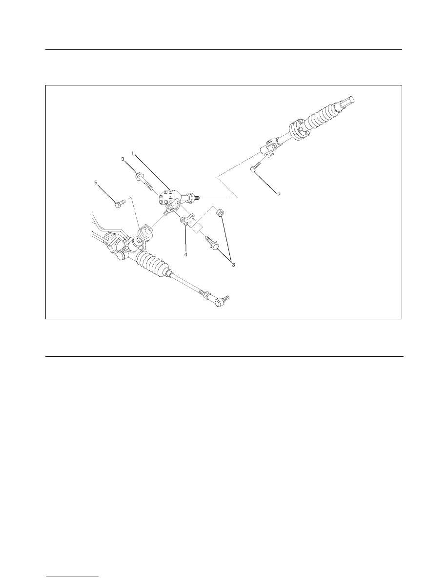
Transfer Gear Assembly
Transfer Gear Assembly and Associated Parts
441RW001
Legend
(1) Transfer Gear Assembly
(2) Bolt, Universal Joint (Steering Shaft Side)
(3) Fixing Bolt Nut
(4) Shim
(5) Bolt, Universal Joint (Steering Unit Side)
Removal
1. Remove universal joint bolt (steering shaft side).
2. Remove universal joint bolt (steering unit side).
3. Loosen fixing bolt and nut and remove transfer gear
assembly with shim.
Inspection and Repair
The transfer gear assembly cannot be disassembled. If
damage or abnormal condition are found, replace to new
ones.
Installation
1. Install transfer gear assembly with shim and tighten
bolt and nut to the specified torque.
Torque: 54 N·m (40 lb ft)
2. Connect universal joint (both side) and tighten the bolt
to the specified torque.
Torque: 31 N·m (23 lb ft)
Нет комментариевНе стесняйтесь поделиться с нами вашим ценным мнением.
Текст