Isuzu Rodeo UE. Service manual — part 337
6E2–103
RODEO 6VD1 3.2L ENGINE DRIVEABILITY AND EMISSIONS
Knock Sensor (KS) System Check
(Engine Knock, Poor Performance, or Poor Economy)
D06RW035–1
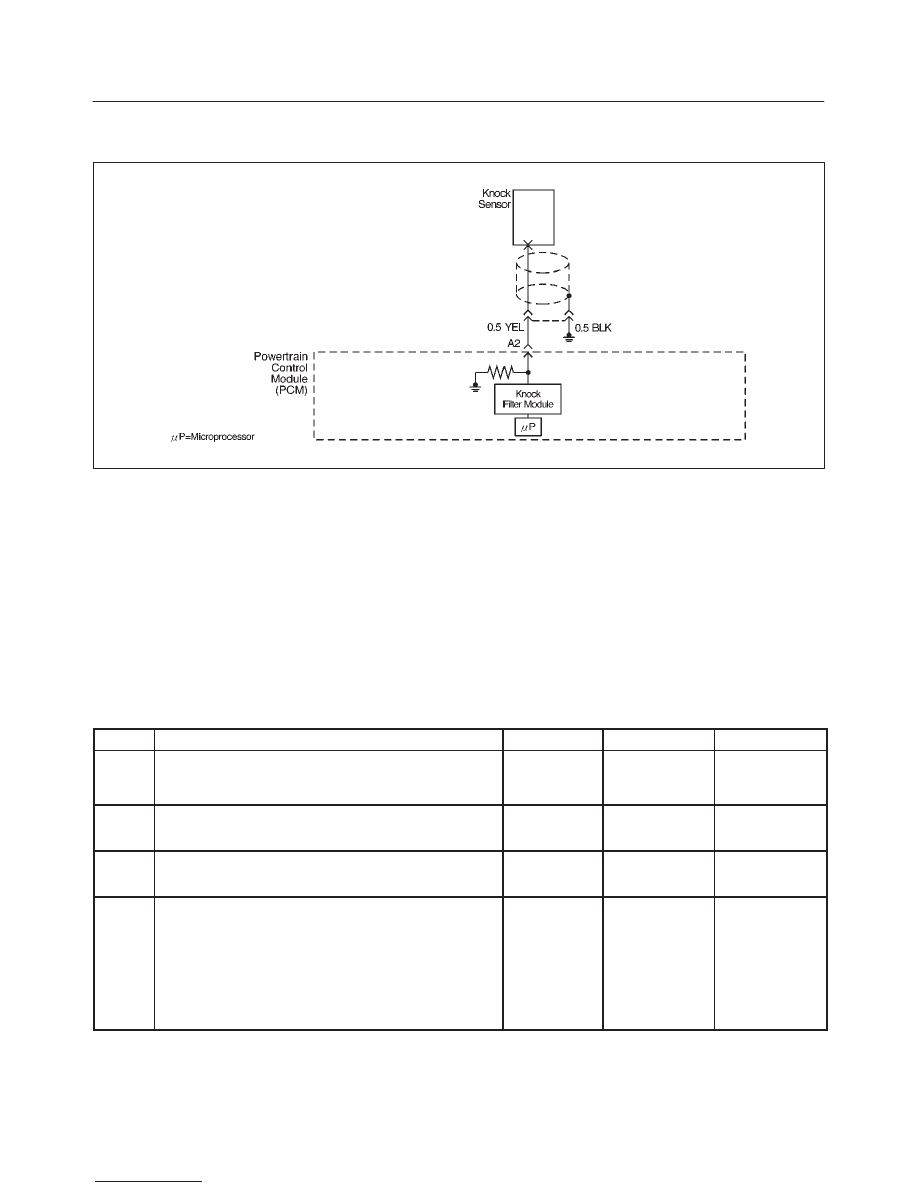
Circuit Description
The knock sensor (KS) sends an AC voltage signal to the
powertrain control module (PCM). As the KS detects
engine knock, the signal to the PCM changes in amplitude
and frequency. The PCM retards timing if the engine
speed is over 900 RPM.
Diagnostic Aids
If the KS system checks OK, but detonation is the
complaint, refer to
Diagnosis, Detonation/Spark Knock.
Test Description
The numbers below refer to the step numbers on the
Diagnostic Chart.
9. The change in signal speed depends on how hard
the tapping is done. Normally there is about 1.5 to
10 mV at PCM pin A2 with the engine off. Loud
tapping should be able to make the reading jump to
20-25 mV AC.
Knock Sensor (KS) System Check
(Engine Knock, Poor Performance, or Poor Economy)
Step
Action
Value(s)
Yes
No
1
Is DTC P0325 or P0327 set?
—
Go to
DTC
P0325 or
DTC P0327
Go to
Step 2
2
Run the engine at 1500 RPM.
Is there an internal engine knock?
—
Go to
Step 3
Go to
Step 4
3
Repair the mechanical problem.
Is the action complete?
—
Verify repair
—
4
1. Install the Tech 2.
2. Turn the ignition “ON.”
3. On the Tech 2 select F0: Data List, F4: Specific
Engine, F3: Misfire.
4. Cycle through the list until “Knock Retard” is
displayed.
Is knock retard at the specified value?
0
°
Go to
Step 5
Go to
Step 6

6E2–104
RODEO 6VD1 3.2L ENGINE DRIVEABILITY AND EMISSIONS
Knock Sensor (KS) System Check
(Engine Knock, Poor Performance, or Poor Economy)
(Cont'd)
Step
No
Yes
Value(s)
Action
5
Replace the PCM.
IMPORTANT: The replacement PCM must be
programmed. Refer to
On–Vehicle Servicein
Powertrain Control Module and Sensorsfor
procedures.
And also refer to latest Service Bulletin.
Check to see if the Latest software is released or not.
And then Down Load the LATEST PROGRAMMED
SOFTWARE to the replacement PCM.
Is the action complete?
—
Verify repair
—
6
1. Start the engine.
2. Monitor the knock retard display on the Tech 2 while
changing the throttle setting to place different loads
on the engine.
Is knock retard at the specified value? (Turn the ignition
“OFF.”)
0
°
Go to
Step 9
Go to
Step 7
7
1. At the rear of the engine, behind the rear fuel
injector on the side, disconnect the 2-wire knock
sensor harness connector.
NOTE: The connector for the knock sensor cannot
easily be removal unless common chamber is
removed. (Knock Sensor is on Right side of block).
Also, there are two (2) shield grounded wires.
The connector only has one wire (Yellow). Please
use another method.
2. Attach the positive lead of DVM to B+.
3. On the main harness side of the connector, use the
negative lead of the DVM to probe the connector pin
that is connected to black wire.
Dose the DVM indicate the specified value?
(Reconnect the knock sensor harness.)
B+
Go to
Step 9
Go to
Step 8
8
Repair the open black wire ground for the shield which
prevents stray electromagnetic pulses from affecting
the knock signal.
Is the action complete?
—
Verify repair
—
9
1. Reconnect the wire harness if it was previously
disconnected in Step 7.
2. Set a DVM to AC voltage.
3. With the DVM, backprobe the PCM connector at
A2.
4. Tap the engine lift bracket with a socket extension.
Did the DVM show an increase in AC voltage while
tapping on the lift bracket?
—
System OK
Go to
Step 10
10
Replace the knock sensor.
Is the action complete?
—
Verify repair
—
6E2–105
RODEO 6VD1 3.2L ENGINE DRIVEABILITY AND EMISSIONS
Exhaust Gas Recirculation (EGR) System Check
D06RW055
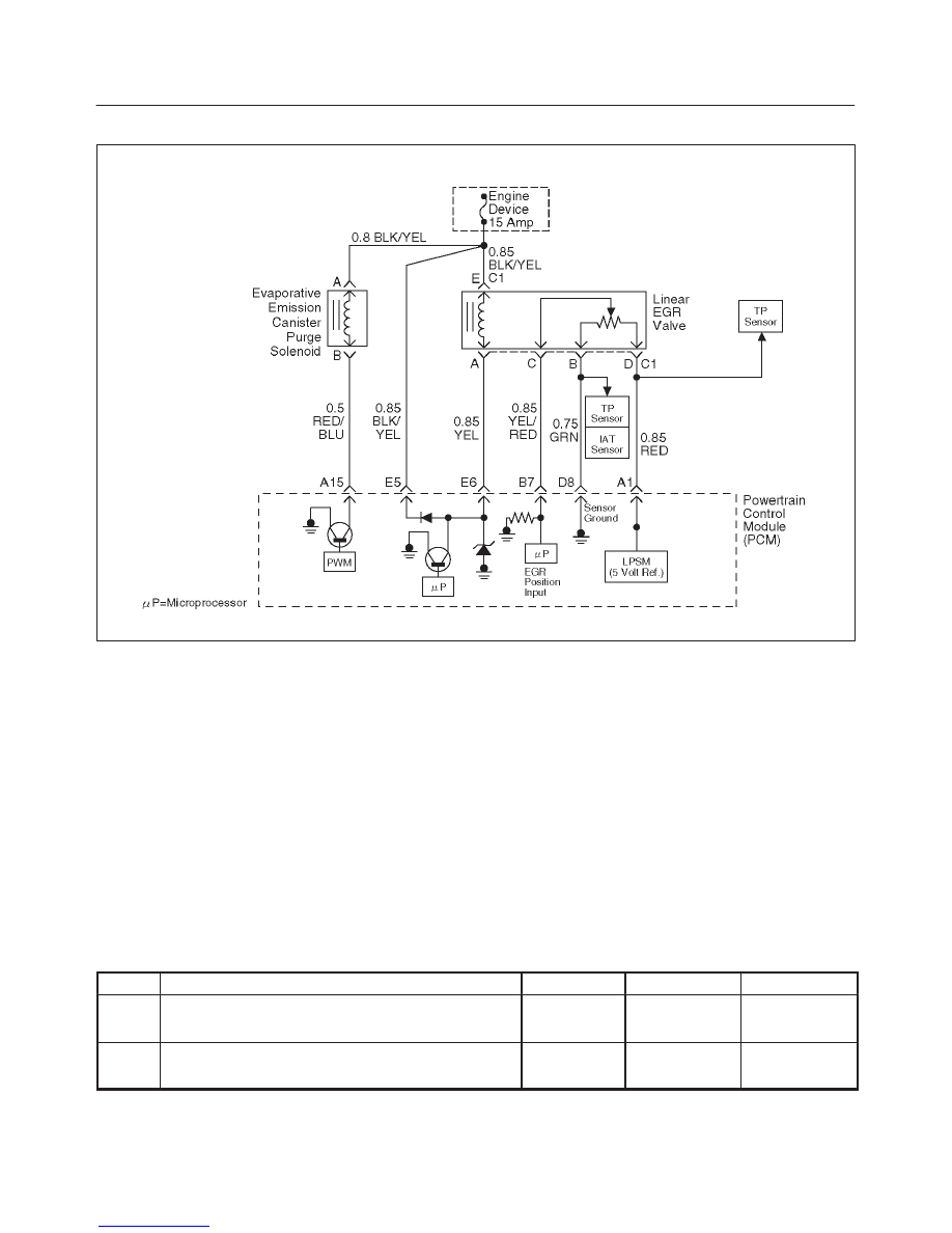
Circuit Description
A properly operation exhaust gas recirculation (EGR)
system will directly affect the air/fuel requirements of the
engine. Since the exhaust gas introduced into the air/fuel
mixture is an inert gas (contains very little or no oxygen),
less fuel is required to maintain a correct air/fuel ratio.
Introducing exhaust gas into the combustion chamber
lowers combustion temperatures and reduces the
formation of oxides of nitrogen (NOx) in the exhaust gas.
Lower combustion temperatures also prevent detonation.
If the EGR pintle were to stay closed, the inert exhaust
gas would be replaced with air and the air/fuel mixture
would be leaner. The powertrain control module (PCM)
would compensate for the lean condition by adding fuel,
resulting in higher long term fuel trim values.
Diagnostic Aids
The EGR valve chart is a check of the EGR system. An
EGR pintle constantly in the closed position could cause
detonation and high emissions of NOx. It could also result
in high long term fuel trim values in the open throttle cell,
but not in the closed throttle cell. An EGR pintle
constantly in the open position would cause a rough idle.
Also, an EGR mounted incorrectly (rotated 180
°
) could
cause rough idle. Check for the following items:
f
EGR passages – Check for restricted or blocked EGR
passages.
f
Manifold absolute pressure sensor – A manifold
absolute pressure sensor may shift in calibration
enough to affect fuel delivery. Refer to
Manifold
Absolute Pressure Output Check.
Exhaust Gas Recirculation (EGR) System Check
Step
Action
Value(s)
Yes
No
1
Check the EGR valve for looseness.
Is the EGR valve Loose?
—
Go to
Step 2
Go to
Step 3
2
Tighten the EGR valve.
Is the action complete?
—
Verify repair
—

6E2–106
RODEO 6VD1 3.2L ENGINE DRIVEABILITY AND EMISSIONS
Exhaust Gas Recirculation (EGR) System Check
(Cont'd)
Step
No
Yes
Value(s)
Action
3
1. Place the transmission selector in Park or Neutral.
2. Start the engine and idle until warm.
3. Using a Tech 2, command EGR “50% ON.” (Refer to
Miscellaneous Test)
Does the engine idle rough and lose RPMs?
—
EGR system
working
properly. No
problem
found.
Go to
Step 4
4
1. Engine “OFF.”
2. Ignition “ON.”
3. Using a test light to ground, check the EGR harness
between the EGR valve and the ignition feed.
Does the test light illuminate?
—
Go to
Step 6
Go to
Step 5
5
Repair the EGR harness ignition feed.
Was the problem corrected?
—
Verify repair
Go to
Step 6
6
1. Remove the EGR valve.
2. Visually and physically inspect the EGR valve
pintle, valve passages and adapter for excessive
deposits, obstructions or any restrictions.
Does the EGR valve have excessive deposits,
obstructions or any restrictions?
—
Go to
Step 7
Go to
Step 8
7
Clean or replace EGR system components as
necessary.
Was the problem corrected?
—
Verify repair
Go to
Step 8
8
1. Ground the EGR valve metal case to battery (–).
2. Using a Tech 2, command EGR “ON” and observe
the EGR valve pintle for movement.
Does the EGR valve pintle move according to
command?
—
Go to
Step 9
Go to
DTC
P1406 chart
9
1. Remove the EGR inlet and outlet pipes from the
intake and exhaust manifolds.
2. Visually and physically inspect manifold EGR ports
and EGR inlet and outlet pipes for blockage or
restriction caused by excessive deposits or other
damage.
Do the manifold EGR ports or inlet and outlet pipes
have excessive deposits, obstructions, or any
restrictions?
—
Go to
Step 10
EGR system
working
properly. No
problem
found.
10
Clean or replace EGR system components as
necessary.
Is the action complete?
—
Verify repair
—
Нет комментариевНе стесняйтесь поделиться с нами вашим ценным мнением.
Текст