Isuzu Rodeo UE. Service manual — part 642
9J1–5
RESTRAINT CONTROL SYSTEM
SRS Diagnostic System Check
Step
Action
Yes
No
1
Note the “AIR BAG” warning lamp when ignition switch is turned
“ON.”
Does the “AIR BAG” warning lamp flash seven (7) times?
Go to Step 2
Go to Step 3
2
Note the “AIR BAG” warning lamp after it flashed 7 times.
Does the “AIR BAG” warning lamp go “OFF”?
Go to Step 4
Go to Step 5
3
Note the “AIR BAG” warning lamp when ignition switch is turned
“ON.”
Does the “AIR BAG” warning lamp come “ON” steady?
Go to Chart B.
Go to Chart C.
4
1. Ignition switch “OFF.”
2. Connect a scan tool to data link connector.
3. Follow direction given in the scan tool instruction manual.
4. Ignition switch “ON.”
5. Request the SRS diagnostic trouble code display recode all
history diagnostic trouble code(s) specify as such, on repair
order.
Is diagnostic trouble code(s) displayed?
Ignition switch
“OFF.”
When DTC 71 is
set, go to DTC 71
chart.
For all other
history codes
refer to
“Diagnostics
Aids” for that
specific DTC.
A history DTC
indicates the
malfunction has
been repaired or
is intermittent.
SRS is functional
and free of
malfunctions, no
further diagnosis
is required.
If scan tool
indicates “No
Data Received,”
refer to chassis
electrical section.
5
1. Ignition switch “OFF.”
2. Connect a scan tool to data link connector.
3. Follow directions as given in the scan tool instruction manual.
4. Ignition switch “ON.”
5. Request the SRS diagnostic trouble code display, recode all
diagnostic trouble code(s), specifying as current or history on
repair order.
Is diagnostic trouble code(s) displayed?
Ignition switch
“OFF.”
When DTC 53 is
set, go to DTC 53
chart.
When DTC 51 is
set, go to DTC 51
chart.
When DTC 19 is
set, go to DTC 19
chart.
When DTC 25 is
set, go to DTC 25
chart.
Diagnose
remaining current
DTCs from
lowest to
highest.When
only history DTCs
exist, Refer to
“Diagnostics
Aids” for that
specific DTC.
A history DTC
indicates the
malfunction has
been repaired or
is intermittent.
If scan tool
indicates “No
Data Received,”
refer to chassis
electrical section.
RESTRAINT CONTROL SYSTEM
9J1–6
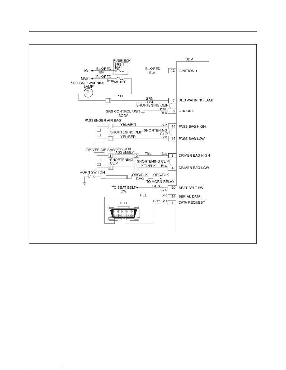
Chart A SDM Integrity Check
D09RW002
Circuit Description:
When the SDM recognizes “ignition 1” voltage, applied to
terminals “12”, is greater than 9 volts, the “AIR BAG”
warning lamp is flashed 7 times to verify operation. At this
time the SDM performs “Turn–ON” tests followed by
“Continuous Monitoring” tests. When a malfunction is
detected, the SDM sets a current diagnostic trouble code
and illuminates the “AIR BAG” warning lamp. The SDM
will clear current diagnostic trouble codes and move them
to a history file when the malfunction is no longer detected
and/or the ignition switch is cycled, except for DTCs 51,
53 and 71. DTC 71 can only be cleared using a scan tool
“Clear Codes” command in case that the malfunction on
DTC 71 has been solved and no DTCs 51 and 53 were
remained. DTCs 51, 53 and 71 can not be cleared after a
“Clear Codes” command is issued.
Chart Test Description:
Number(s) below refer to step number(s) on the
diagnostic chart:
1. This test confirms a current malfunction. If no
current malfunction is occurring (history DTC set)
the “Diagnostic Aids” for the appropriate diagnostic
trouble code should be referenced. The SDM
should not be replaced for a history diagnostic
trouble code.
2. This test checks for a malfunction introduced into the
SRS during the diagnostic process. It is extremely
unlikely that a malfunctioning SDM would cause a
new malfunction to occur during the diagnostic
process.
3. When all circuitry outside the SDM has been found
to operate properly, as indicated by the appropriate
diagnostic chart, then and only then should the SDM
be replaced.

9J1–7
RESTRAINT CONTROL SYSTEM
Chart A SDM Integrity Check
WARNING: DURING SERVICE PROCEDURES. BE VERY CAREFUL WHEN HANDLING A SENSING AND
DIAGNOSTIC MODULE (SDM). NEVER STRIKE OR JAR THE SDM. NEVER POWER UP THE SRS WHEN THE
SDM IS NOT RIGIDLY ATTACHED TO THE VEHICLE. ALL SDM AND MOUNTING BRACKET FASTENERS MUST
BE CAREFULLY TORQUED AND THE ARROW MUST BE POINTING TOWARD THE FRONT OF THE VEHICLE
TO ENSURE PROPER OPERATION OF THE SRS. THE SDM COULD BE ACTIVATED WHEN POWERED WHILE
NOT RIGIDLY ATTACHED TO THE VEHICLE WHICH COULD CAUSE DEPLOYMENT AND RESULT IN
PERSONAL INJURY.
Step
Action
Yes
No
1
1. This chart assumes that the “SRS Diagnostic System Check”
and either a symptom chart or a diagnostic trouble code chart
diagnosis have been performed When all circuitry outside the
SDM has been found to operate properly, as indicated by the
appropriate diagnostic chart, and the symptom or DTC
remains current, the following diagnostic procedures must be
performed to verify the need for SDM Replacement.
2. Ignition switch “OFF.”
3. Reconnect all SRS components, ensure all components are
properly mounted.
4. Ensure the ignition switch has been “OFF” for at least 15
seconds.
5. Note “AIR BAG” warning lamp as ignition switch is turned
“ON.”
Does warning lamp flash 7 times then go “OFF”?
The symptom or
DTC is no longer
occurring.
Clear SRS
diagnostic trouble
codes.
Repeat the “SRS
Diagnostic
System Check.”
Go to Step 2
2
Using a scan tool, request diagnostic trouble code display.
Is the same symptom or DTC occurring as was when the “SRS
Diagnostic System Check ” was first performed?
Ignition switch
“OFF.”
Go to the
appropriate chart
for the indicated
malfunction.
Go to Step 3
3
1. Clear “SRS Diagnostic Trouble Codes.”
2. Ignition switch “OFF” for at least two minutes.
3. Note “AIR BAG” warning lamp as ignition switch is turned
“ON.”
Does warning lamp flash 7 times then go “OFF”?
SRS is functional
and free of
malfunctions.
No further
diagnosis is
required.
Go to Step 4
Ignition switch
“OFF.”
Replace SDM.
Go to Step 4
4
Reconnect all SRS components, ensure all components are
properly mounted.
Was this step finished?
Repeat the “SRS
Diagnostic
System Check.”
Go to Step 4

RESTRAINT CONTROL SYSTEM
9J1–8
Chart B “AIR BAG” Warning Lamp Comes “ON” Steady
D09RW002
Circuit Description:
When the ignition switch is first turned “ON”, “ignition 1”
voltage is applied from the “MA01” meter fuse to “AIR
BAG”, warning lamp which is connected to “SRS warning
lamp”, terminal “7”. The “SRS–1” fuses apply system
voltage to the “ignition 1” inputs, terminals “12”. The SDM
responds by flashing the “AIR BAG” warning lamp 7
times. If “ignition 1” voltage is less than 9 volts, the “AIR
BAG” warning lamp will come “ON” solid with no DTCs
set.
Chart Test Description:
Number (s) below refer to step number (s) on the
diagnostic chart.
2. This test checks for an open in the “ignition 1” circuit
to the SDM.
3. This test checks for the voltage of “ignition 1.”
4. This test determines whether the malfunction is a
short to ground in CKT IB04 – GRN.
Нет комментариевНе стесняйтесь поделиться с нами вашим ценным мнением.
Текст