Isuzu Rodeo UE. Service manual — part 511

7B–76
MANUAL TRANSMISSION
f
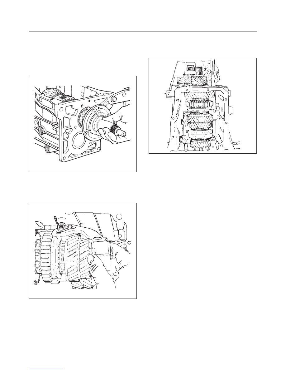
Look for evidence of gear clash on both the
synchronizer sleeve teeth or the clutch teeth on the
speed gear.
226RS124
Finally, look at the synchronizer sleeve and speed
gear clutch tooth area for cause of “hopout”.
226RS125
Reassembly
1. Use a hydraulic press and the J–6133–01 installer to
press the counter shaft rear bearing assembly(20)
onto the counter shaft(21). Use tool J–37357 to
support the counter shaft in the transmission
case(22).
226RS126
2. Install the counter shaft rear bearing outer race(19)
and retainer(17) without the shim.
226RS127
f
Tighten the retainer bolts, using a 13 mm socket (or
a T–40 bit) and a torque wrench.
Torque: 20 N·m (15 lb ft)

MANUAL TRANSMISSION
7B–77
f
Mount a dial indicator on the case and set it up to
measure counter shaft end play.
Move the counter shaft up and down and read the
total amount of indicator travel.
226RS128
f
Select shim which is the same thickness as the
indicator reading, or up to 0.004 inch less than the
reading.
Counter Shaft
Selective Shims
Thickness
Thickness
mm
(inches)
mm
(inches)
2.553
(0.1005)
3.239
(0.1275)
2.59
(0.102)
3.28
(0.129)
2.629
(0.1035)
3.315
(0.1305)
2.67
(0.105)
3.35
(0.132)
2.705
(0.1065)
3.391
(0.1335)
2.74
(0.108)
3.43
(0.135)
2.781
(0.1095)
3.467
(0.1365)
2.82
(0.111)
3.51
(0.138)
2.858
(0.1125)
3.543
(0.1395)
2.90
(0.114)
3.58
(0.141)
2.934
(0.1155)
3.620
(0.1425)
2.97
(0.117)
3.66
(0.144)
3.010
(0.1185)
3.696
(0.1455)
3.05
(0.120)
3.73
(0.147)
3.086
(0.1215)
3.772
(0.1485)
3.12
(0.123)
3.81
(0.150)
3.162
(0.1245)
3.848
(0.1515)
3.20
(0.126)
3.886
(0.1530)
f
Remove the counter shaft rear bearing retainer and
outer race.
3. Install the reverse idler shaft(18), gear(18), and
O–ring(18).
Use a 3/16–inch diameter pin punch and hammer to
install the reverse idler shaft roll pin(18).
226RS129
4. Install the counter shaft rear bearing outer race(19),
shim(17) and retainer(17).
Tightening the bolts.
Torque: 20 N·m (15 lb ft)
226RS130
5. Bend the lock tabs on the retainer, using a punch and
hammer.
6. Install the mainshaft assembly(16) into the case.
7. Install the mainshaft rear bearing outer race(15) into
the rear of the case.
8. Install 4th speed blocking ring(14) onto the front of the
mainshaft.
Install the mainshaft thrust race(14), bearing(14), and
spacer(14) onto the front of the mainshaft.
Apply pertoleum jelly to the mainshaft pilot bearing
rollers(14) (there are 15 rollers) and install them into
the input shaft.
7B–78
MANUAL TRANSMISSION
9. Install the input shaft(13) onto the front of the
mainshaft.
10. Install the input bearing retainer(12) and bearing
outer race(12) without shim onto the front of the case.
Tighten the four bolts, using a 13 mm socket and a
torque wrench.
Torque: 20 N·m (15 lb ft)
220RS058
11. Install the 5th speed drive gear(10) and 5th
synchronizer blocking ring(10) on the rear of the
counter shaft.
12. Install the 5–R lever with reverse fork(9) and spring(9)
into the case.
230RS023
13. Assemble the 5th synchronizer and rail/fork and
install them as follows:
f
Guide the rail(8) through the reverse fork(9) and
into the front of the case.
226RS131
f
Push the 5th synchronizer assembly(8) onto the
splines of the counter shaft together with 5th shift
fork and rail(8).
f
Install the reverse blocking ring, reverse cone(8),
splined washer(8) and 5th synchronizer snap
ring(8).
f
Align the slot of the 5–R shift lever with the roller of
the 5th shift rail.
14. Install oiling funnel(4).
15. Coat the threads of the 5–R lever pivot bolt(7) with
sealer and install it(7) into the case. Make sure that
the 5–R lever is properly aligned with the pivot bolt.
Tighten the pivot bolt, using T–50 bit and a torque
wrench.
Torque: 27 N·m (20 lb ft)

MANUAL TRANSMISSION
7B–79
16. Install the 5–R lever clip(6) using a pair of
needle-nose pliers.
Use a pair of needle nose pliers to attach the reverse
fork spring to its pin inside the case.
Check the operation of the 5–R shift mechanism at
this time.
230RS024
17. Install the 5th driven gear snap ring(11), using snap
ring pliers.
Install the clip(11) and speedometer drive gear(11)
onto the rear of the mainshaft, using installer
J–6133–01 and a hammer. Be sure the speedometer
gear retaining clip is fully seated.
226RS132
18. Install the slip yoke snap ring(11) onto the end of the
mainshaft, using a pair of snap ring pliers.
19. Apply a 3 mm (1/8 in) bead of RTV sealant on the
sealing surface of the shift cover.
Make sure that the 1–2 and 3–4 synchronizer sleeves
are in Neutral position, as well as the 5–R shift lever.
Lower the cover onto the case, allowing the 1–2 and
3–4 forks to slide onto their sleeves. Slide the shift
cover assembly(5) toward the 5–R lever side just
before the cover contacts the case.
230RS025
Install the ten cover-to-case bolts, beginning with the
two alignment–type bolts, using a 10 mm socket and
a torque wrench.
Torque: 14 N·m (10 lb ft)
20. Must align reverse cone with the tab(8) in the “Up” (12
o’clock) position.
226RS133
Нет комментариевНе стесняйтесь поделиться с нами вашим ценным мнением.
Текст