Isuzu Rodeo UE. Service manual — part 384
6E2–291
RODEO 6VD1 3.2L ENGINE DRIVEABILITY AND EMISSIONS
DTC P0352 – Ignition 2 Control Circuit
(Cont'd)
Step
No
Yes
Value(s)
Action
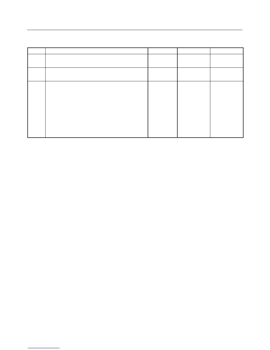
11
Check for an open ignition control circuit 2.
Was the ignition control circuit open?
—
Go to
Step 12
Go to
Step 13
12
Repair the open ignition control circuit.
Is the action complete?
—
Verify repair
—
13
Replace the PCM.
IMPORTANT: The replacement PCM must be
programmed. Refer to
On-Vehicle Service in
Powertrain Control Module and Sensors for
procedures.
And also refer to latest Service Bulletin.
Check to see if the Latest software is released or not.
And then Down Load the LATEST PROGRAMMED
SOFTWARE to the replacement PCM.
Is the action complete?
—
Verify repair
—
6E2–292
RODEO 6VD1 3.2L ENGINE DRIVEABILITY AND EMISSIONS
Diagnostic Trouble Code (DTC) P0353 Ignition 3 Control Circuit
D06RX018
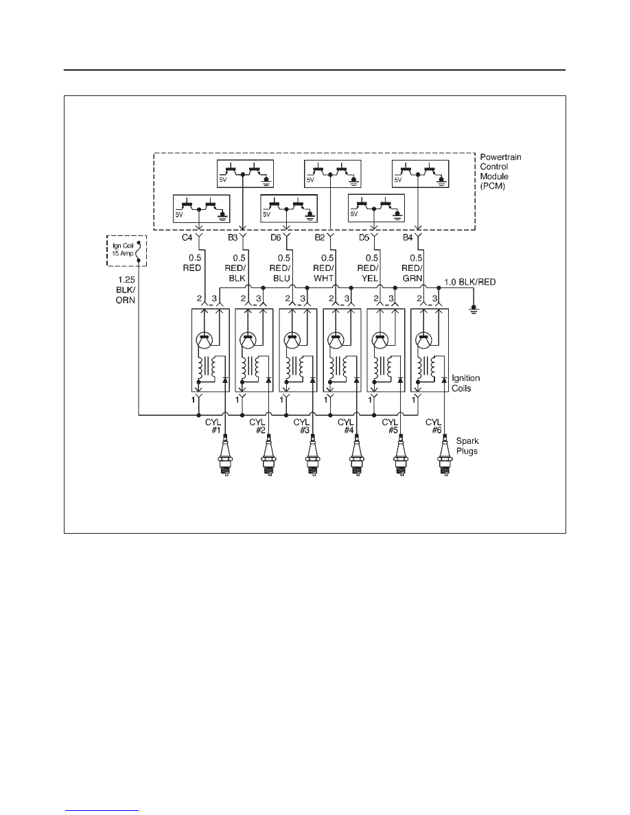
Circuit Description
The powertrain control module’s (PCM) control circuit 3
provides a zero-volt or a 5-volt output signal to the ignition
coil. The normal voltage on the circuit is zero volts. When
the ignition coil receives the 5-volt signal from the PCM, it
provides a ground path for the B+ supply to the primary
side of the number 3 ignition coil. When the PCM shuts off
the 5 volts to the ignition coil, the ignition coil turns “OFF.”
This causes the ignition coil primary magnetic field to
collapse, producing a voltage in the secondary coil which
fires the spark plug.
The circuit between the PCM and ignition coil is monitored
for an open circuit, short to voltage, and short to ground.
When the PCM detects a problem on ignition control
circuit 3, it will set a DTC P0353.
Conditions for Setting the DTC
f
The ignition is “ON.”
f
The engine is turning, determined by the 58X
crankshaft position input signal.
f
The output voltage is not equal to 5 volts when output
is “ON.”
f
The output voltage is not equal to 0 volts when output
is “OFF.”
f
Twenty test failures occur within 40 samples of
continuous spark events.
Action Taken When the DTC Sets
f
The PCM will illuminate the malfunction indicator lamp
(MIL) the first time the fault is detected.
f
The PCM will store conditions which were present
when the DTC was set as Freeze Frame and in the
Failure Records data.
Conditions for Clearing the MIL/DTC
f
The PCM will turn the MIL “OFF” on the third
consecutive trip cycle in which the diagnostic has been
run and the fault condition is no longer present.
f
A history DTC P0353 will clear after 40 consecutive
warm-up cycles occur without a fault.

6E2–293
RODEO 6VD1 3.2L ENGINE DRIVEABILITY AND EMISSIONS
f
DTC P0353 can be cleared by using the Tech 2 “Clear
Info” function or by disconnecting the PCM battery
feed.
Diagnostic Aids
Check for the following conditions:
f
Poor connection at PCM – Inspect the harness
connectors for backed-out terminals, improper mating,
broken locks, improperly formed or damaged
terminals, and poor terminal-to-wire connections.
f
Damaged harness – Inspect the wiring harness for
damage. If the harness appears to be OK, observe the
Tech 2 display related to DTC P0353 while moving the
connector and wiring related to the ignition system. A
change in the display will indicate the location of the
fault.
Reviewing the Failure Records vehicle mileage since the
diagnostic test last failed may help determine how often
the condition that caused the DTC to be set occurs. This
may assist in diagnosing the condition.
DTC P0353 – Ignition 3 Control Circuit
Step
Action
Value(s)
Yes
No
1
Was the “On-Board Diagnostic (OBD) System Check”
performed?
—
Go to
Step 2
Go to
OBD
System
Check
2
1. Ignition “ON,” engine “OFF.”
2. Review and record Tech 2 Failure Records data.
3. Operate the vehicle within Failure Record
conditions as noted.
4. Use a Tech 2 to monitor the “DTC” information for
DTC P0353 until the DTC P0353 test runs.
5. Note the test result.
Does the Tech 2 indicate DTC P0353 failed this ignition
cycle?
—
Go to
Step 3
Go to
Diagnostic
Aids
3
Check for faulty connection at ignition coil.
Was a problem found?
—
Verify repair
Go to
Step 4
4
Check for faulty connection at PCM connector.
Was a problem found?
—
Verify repair
Go to
Step 5
5
1. Ignition “ON,” engine “OFF.”
2. Back probe the ignition control circuit 3 at the PCM
with a DVM.
Is the voltage near the specified value?
25-55 mV
Go to
Step 6
Go to
Step 9
6
1. Ignition “ON,” engine running.
2. Back probe the ignition control circuit at the PCM for
the cylinder being tested.
Is the voltage in the specified range, rapidly toggling
back and forth to a reading 20-50 mV higher?
100-180 mV
Go to
Step 7
Go to
Step 13
7
1. Ignition “OFF.”
2. Disconnect the 3-pin connector at the ignition coil.
3. Check ignition control circuit 3 voltage at the ignition
coil connector while cranking the engine.
Does the voltage measure between the specified
values?
200-1200 mV
Go to
Step 8
Go to
Step 11
8
Replace the ignition coil.
Is the action complete?
—
Verify repair
—
9
1. Ignition “OFF.”
2. Disconnect the PCM and the ignition coil.
3. Check ignition control circuit 3 for short to ground.
Was a problem found?
—
Verify repair
Go to
Step 10
10
Check ignition control circuit 3 for short to voltage.
Was a problem found?
—
Verify repair
Go to
Step 13
6E2–294
RODEO 6VD1 3.2L ENGINE DRIVEABILITY AND EMISSIONS
DTC P0353 – Ignition 3 Control Circuit
(Cont'd)
Step
No
Yes
Value(s)
Action
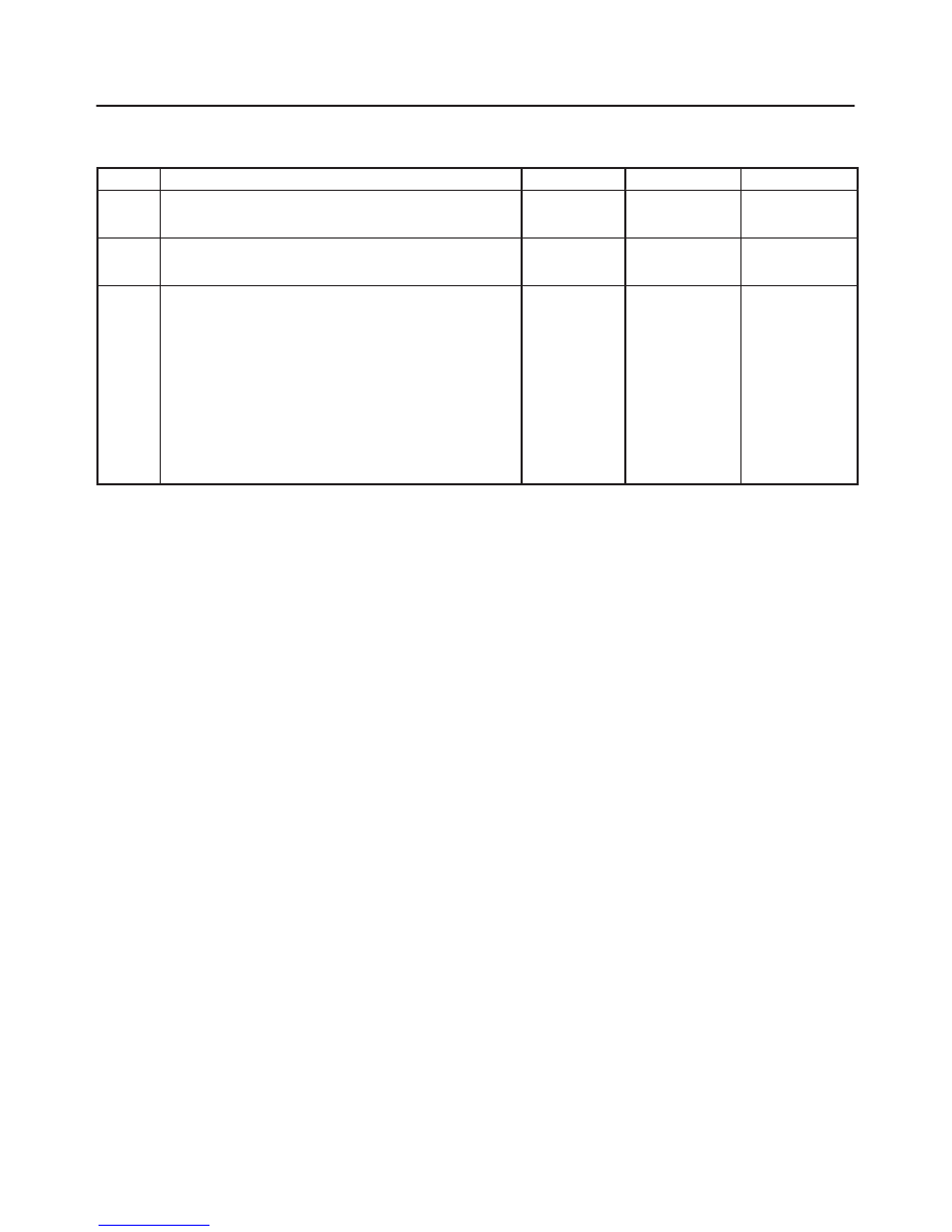
11
Check for an open ignition control circuit 3.
Was the ignition control circuit open?
—
Go to
Step 12
Go to
Step 13
12
Repair the open ignition control circuit.
Is the action complete?
—
Verify repair
—
13
Replace the PCM.
IMPORTANT: The replacement PCM must be
programmed. Refer to
On-Vehicle Service in
Powertrain Control Module and Sensors for
procedures.
And also refer to latest Service Bulletin.
Check to see if the Latest software is released or not.
And then Down Load the LATEST PROGRAMMED
SOFTWARE to the replacement PCM.
Is the action complete?
—
Verify repair
—
Нет комментариевНе стесняйтесь поделиться с нами вашим ценным мнением.
Текст