Isuzu Rodeo UE. Service manual — part 101
5A–27
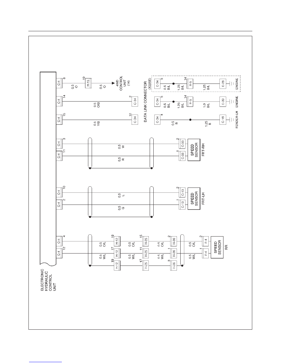
BRAKE CONTROL SYSTEM
D08RX109
5A–28
BRAKE CONTROL SYSTEM
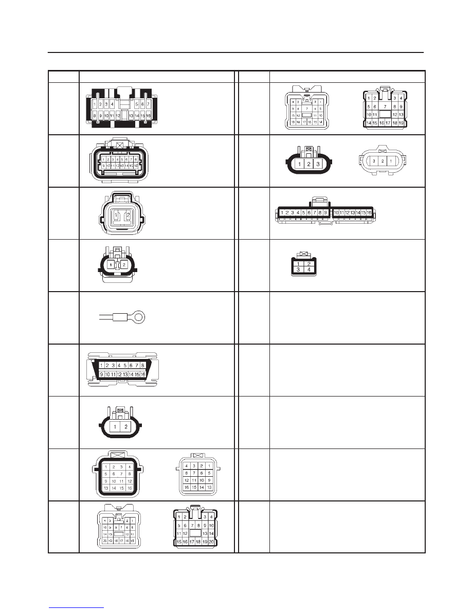
Connector List
No.
Connector face
No.
Connector face
B-19
H-13
H-14
C-4
H-26
C-5
I-1
C-13
C-33
I-18
C-16
C-36
E-28
E-30
C-34
F-4
H-5
H-12
H-15
H-25
5A–29
BRAKE CONTROL SYSTEM
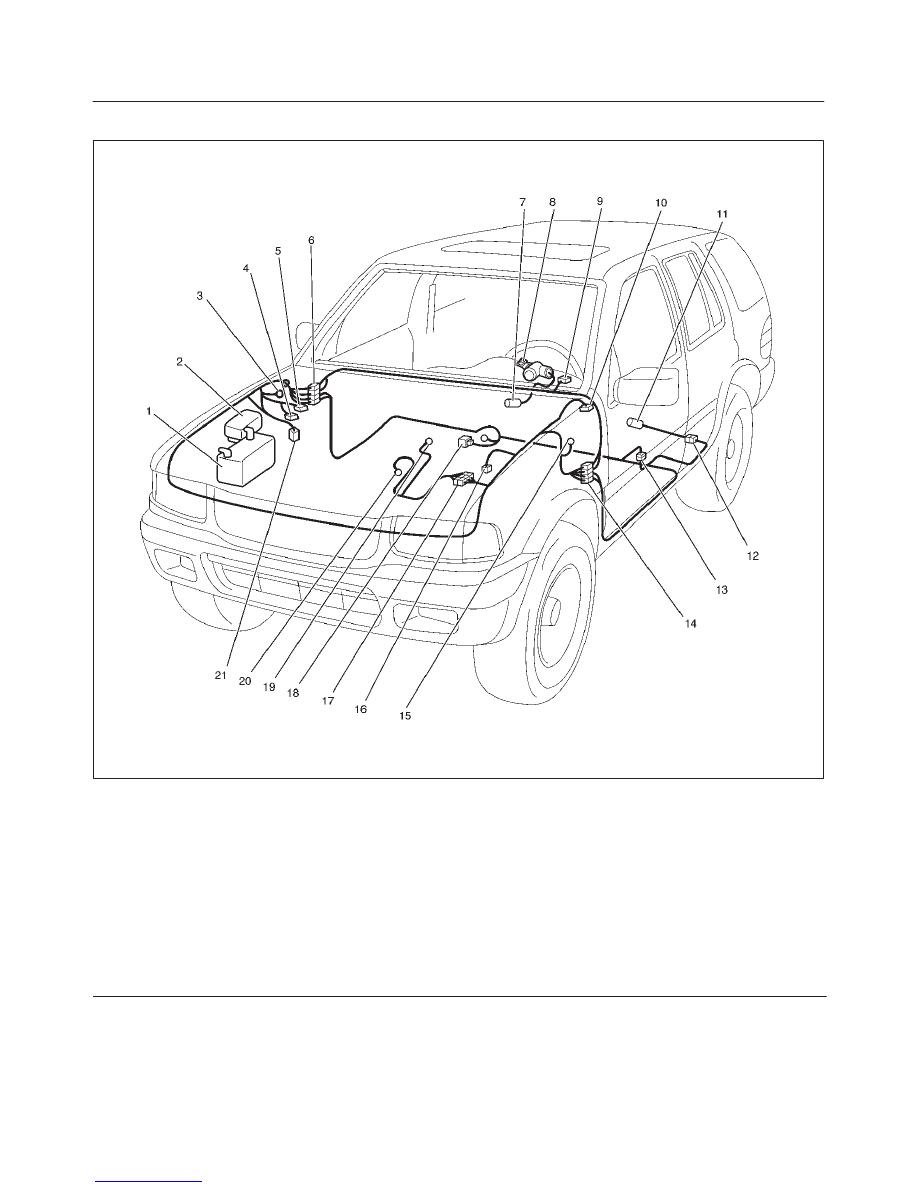
Part Location
D08RX107
Legend
(1) Battery
(2) Fuse & Relay Box
(3) C–36
(4) C–5
(5) C–4
(6) H–12, 13, 14
(7) I–18
(8) Starter Switch
(9) I–1
(10) C–34
(11) F–4
(12) H–26
(13) H–25
(14) H–15
(15) C–16
(16) C–13
(17) H–5
(18) B–19
(19) E–30 (6VD1)
(20) E–28 (X22SE)
(21) C–33
5A–30
BRAKE CONTROL SYSTEM
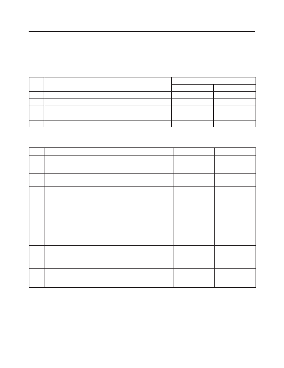
Symptom Diagnosis
The symptoms that cannot be indicated by warning light
can be divided in the following five categories:
1. ABS works frequently but vehicle does not
decelerate.
2. Uneven braking occurs while ABS works.
3. The wheels lock during braking.
4. Brake pedal feel is abnormal.
5. Braking sound (from EHCU) is heard while not
braking.
These are all attributable to problems which cannot be de-
tected by EHCU self-diagnosis. Use the customer com-
plaint and a test to determine which symptom is present.
Then follow the appropriate flow chart listed below.
No
Symptom
Diagnostic Flow Charts
No.
Sym tom
Without TECH 2
With TECH 2
1
ABS works frequently but vehicle does not decelerate.
Chart A-1
Chart TA-1
2
Uneven braking occurs while ABS works.
Chart A-2
Chart TA-2
3
The wheels are locked.
Chart A-3
Chart TA-3
4
Brake pedal feel is abnormal.
Chart A-4
—
5
Braking sound (from EHCU) is heard while not braking.
Chart A-5
Chart TA-5
Chart A-1 ABS Works Frequently But Vehicle Does Not Decelerate
Step
Action
Yes
No
1
Is braking force distribution normal between front and rear of
vehicle?
Go to Step 2
Repair brake
parts.
Go to Step 8
2
Are axle parts installed normally?
Go to Step 3
Repair axle parts.
Go to Step 8
3
Is there play in each or any wheel speed sensor?
Repair wheel
speed sensor.
Go to Step 8
Go to Step 4
4
Is there damage, or powered iron sticking to each or any wheel
speed sensor/sensor ring?
Replace sensor
or sensor ring.
Go to Step 8
Go to Step 5
5
Is the output of each wheel speed sensor normal? (Refer to chart
C-1 or TC-1)
Go to Step 6
Replace wheel
speed sensor or
repair harness.
Go to Step 7
6
Is the input of 4WD controller normal?
Go to Step 7
Replace
controller or
repair harness.
Go to Step 7
7
Reconnect all components, ensure all components are properly
mounted.
Was this step finished?
Repeat the “Basic
diagnostic flow
chart”
Go to Step 7
Нет комментариевНе стесняйтесь поделиться с нами вашим ценным мнением.
Текст