Isuzu Rodeo UE. Service manual — part 653
10A–3
CRUISE CONTROL SYSTEM
Clutch Switch
Removal and Installation
Refer to the Clutch Control removal and installation steps
in Clutch section.
Adjustment
1. Turn the clutch switch (1) until the switch plunger is
fully retracted against the clutch pedal arm.
2. Adjust clutch switch by backing it out half a turn and
measure the clearance (4) between the clutch pedal
arm (3) and the clutch switch.
3. Lock the lock nut(2).
4. Connect clutch switch connector.
Clutch Switch (bolt) and Clutch Pedal Clearance
0.5 – 1.5 mm (0.020 – 0.059 in)
203RS016–1
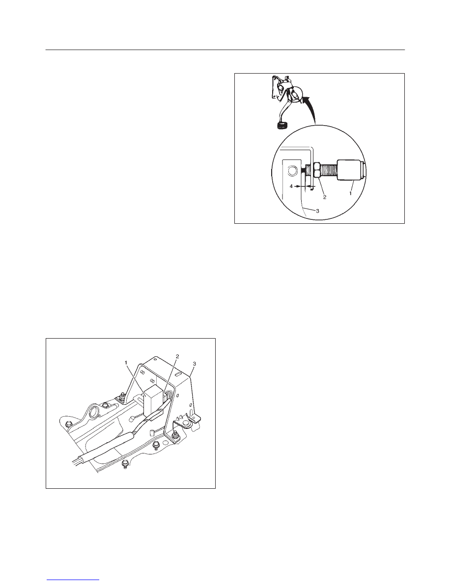
Cruise Control Unit
Removal
1. Disconnect the battery ground cable.
2. Remove the rear console box assembly.
f
Remove four screws.
3. Remove the cover (3).
f
Remove four nuts.
4. Remove the cruise control unit (1).
f
Disconnect the connector (2).
825RX017
Installation
To install, follow the removal steps in the reverse order.
10A–4 CRUISE CONTROL SYSTEM
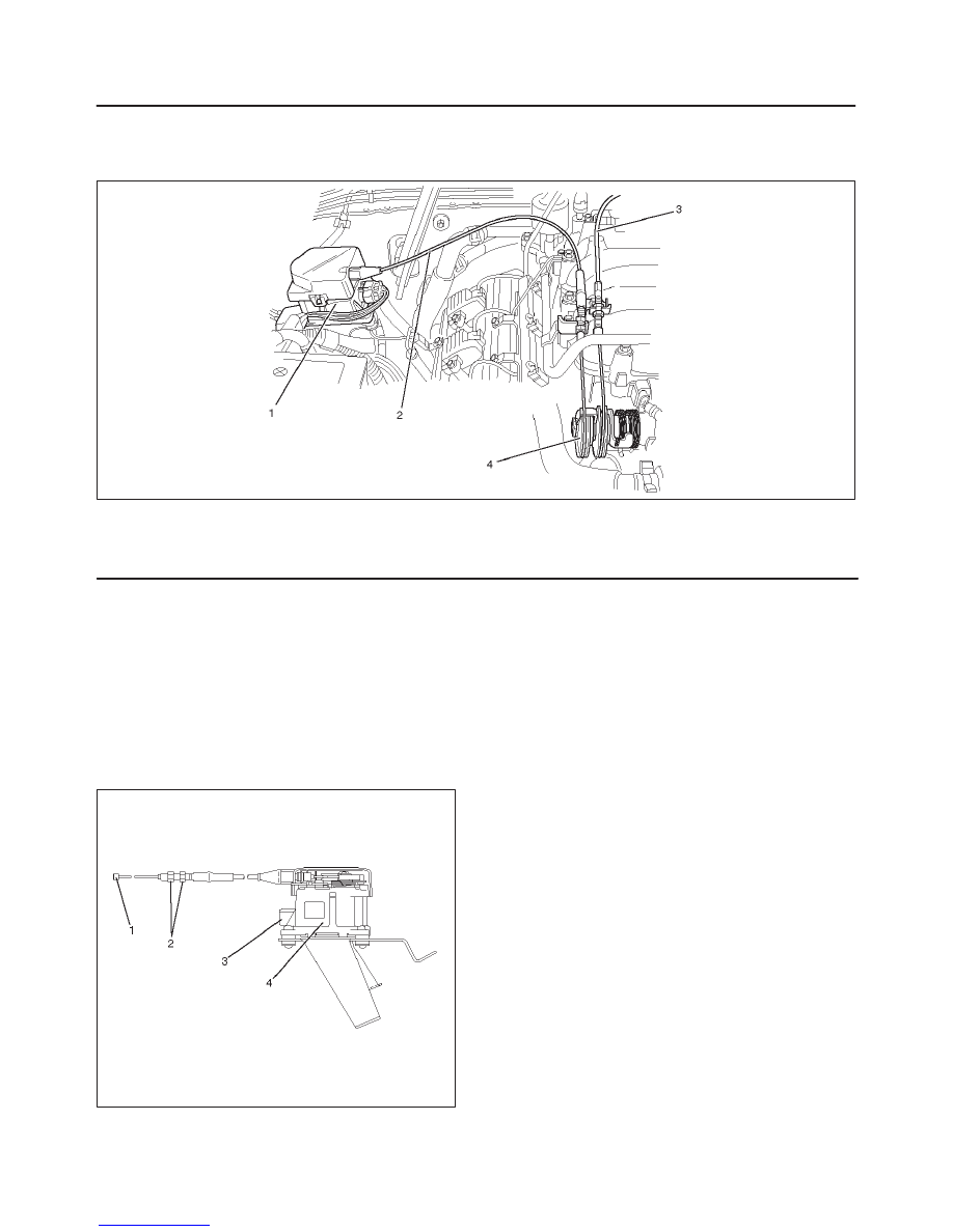
Cruise Actuator
Actuator Cable Diagram
825RW093
Legend
(1) Cruise Actuator Assembly
(2) Cruise Control Cable
(3) Accelerator Cable
(4) Throttle Link (Cruise Control Side)
Removal
1. Disconnect the battery ground cable.
2. Remove the cruise actuator assembly (4).
f
Disconnect the connector (3).
f
Remove the cable end (1) from the throttle link
(cruise control side).
f
Loosen two fixing nuts (2).
f
Remove three actuator assembly fixing screws.
825RW049
Installation
To install, follow the removal steps in the reverse order,
noting the following point:
1. Take care not to bend the cable excessively.
Adjustment
After installing the cruise actuator, the following steps
must be carried out for cruise control cable adjustment.
1. Install the cruise control cable end (3) to the throttle
link (4).
2. Put the screw portion of the cable in the bracket (5).
3. Put the nut (1) to the bracket and then tighten the nut
(2).
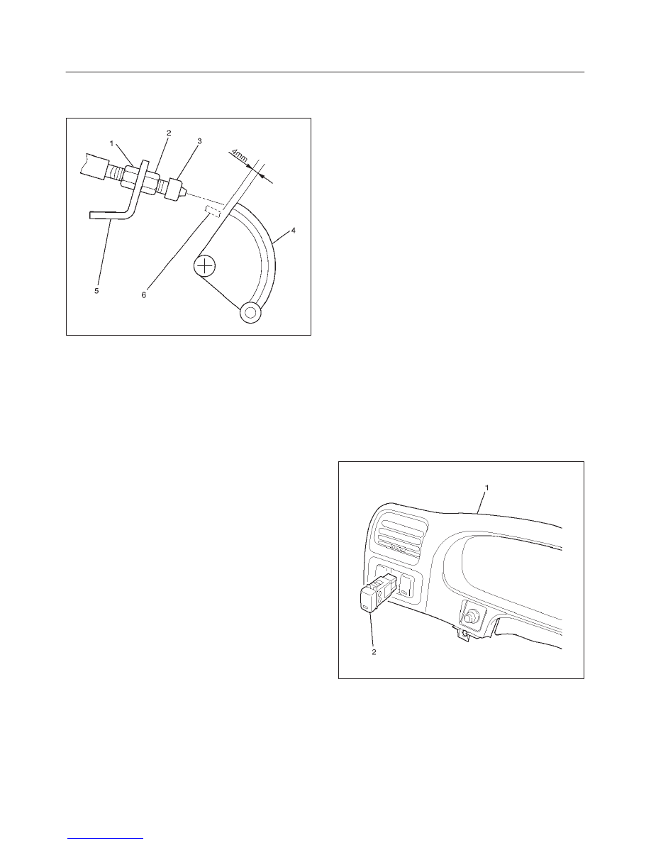
10A–5
CRUISE CONTROL SYSTEM
f
If the distance between the throttle link (4) and the
throttle link lever (6) is out of the specified range,
loosen the nut (2) to adjust it.
035RW140
Mode Switch
Removal and Installation
Refer to the Mode Switch removal and installation steps
in Automatic Transmission section.
Cruise Control Main Switch
Removal
1. Disconnect the battery ground cable.
2. Remove the meter cluster assembly (1).
f
Refer to the Instrument Panel Assembly in Body
Structure section.
3. Remove the rear defogger switch (2).
f
Disconnect the switch connector.
f
To remove the switch, push the lock from the back
side of the instrument panel cluster assembly.
825RW089
Installation
To install, follow the removal steps in the reverse order.
10A–6 CRUISE CONTROL SYSTEM
Cruise Control Switch (Combination Switch)
Removal and Installation
Refer to the Lighting Switch (Combination Switch)
removal and installation steps in Lighting System section.
Нет комментариевНе стесняйтесь поделиться с нами вашим ценным мнением.
Текст