Isuzu Rodeo UE. Service manual — part 183

6E1–103
RODEO X22SE 2.2L ENGINE DRIVEABILITY AND EMISSION
Evaporative (EVAP) Emissions Canister Purge Valve Solenoid Check
Step
Action
Value(s)
Yes
No
1
1. Ignition OFF.
2. Ignition ON, engine OFF.
3. At the throttle body, disconnect the hose that goes
to the pump solenoid.
4. Using a hand vacuum pump with an attached
vacuum gauge J 23738–A, apply vacuum (10” Hg or
34 kPa) to the solenoid.
Does the solenoid hold vacuum?
—
Go to Step 3
Go to Step 2
2
1. Disconnect the solenoid electrical connector.
2. As in Step 1, apply vacuum (10” Hg or 34 kPa) to the
solenoid.
Does the solenoid hold vacuum?
—
Go to Step 4
Go to Step 7
3
1. At the throttle body, put a cap over the vacuum port
where the hose was disconnected for testing. This
is to prevent a vacuum leak when the engine is
started.
2. Ignition OFF.
3. Install the Tech 2.
4. Apply vacuum to the purge solenoid with the hand
vacuum pump.
5. Start the engine, run at 2500 RPM.
6. Using the Tech 2 command the purge solenoid ON.
Did the vacuum drop when the purge was turned on?
—
Go to Step 8
Go to Step 9
4
Check for a short to ground or open in the wire between
the solenoid and the PCM.
Is there a problem?
—
Go to Step 5
Go to Step 6
5
Repair the faulty wire.
Is the action complete?
—
Verify repair
—
6
Replace the PCM.
IMPORTANT: The replacement PCM must be
programmed. Refer to On–Vehicle Service in
Powertrain Control Module and Sensors for
procedures.
and also refer to latest service bulletin.
Check to see if the Latest software is released or not.
And then Down Load the LATEST PROGRAMMED
SOFTWARE to the replacement PCM.
Is the action complete?
—
Verify repair
—
7
Replace the faulty purge solenoid.
Refer to On–Vehicle Service, EVAP Canister Purge
Solenoid.
Is the action complete?
—
Verify repair
—

6E1–104
RODEO X22SE 2.2L ENGINE DRIVEABILITY AND EMISSION
Evaporative (EVAP) Emissions Canister Purge Valve Solenoid Check
(Cont'd)
Step
No
Yes
Value(s)
Action
8
1. Turn the ignition OFF.
2. At the throttle body, install a vacuum gauge where
the hose from the purge solenoid was disconnected
for testing.
3. Start the engine.
4. Stabilize the engine speed at about 2500 RPM.
5. Momentarily snap the throttle open and let it return
to idle.
Is there approximately 10” Hg (34 kPa) of vacuum
available at the EVAP emission canister purge
solenoid?
—
No problem
found in the
EVAP
emission
canister
purge valve
check.
Refer to
Diagnostic
Aids
9
1. Turn the Ignition OFF.
2. Disconnect the solenoid’s electrical connector.
3. Connect a test lamp between the harness
terminals.
4. Turn the Ignition ON.
Does the test lamp light?
—
Go to Step 7
Go to Step 10
10
Probe each terminal of the solenoid valve electrical
connector with a test lamp to ground.
Does the test lamp light on both terminals?
—
Go to Step 11
Go to Step 12
11
Repair the short to voltage in the wire between the
solenoid and the PCM.
Is the action complete?
—
Verify repair
—
12
Does the ignition feed terminals light the test lamp?
—
Go to Step 13
Go to Step 14
13
Check for an open in the wire between the purge
solenoid and the PCM.
Was there an open circuit?
—
Go to Step 15
Go to Step 6
14
Repair the open in the ignition feed wire.
Is the action complete?
—
Verify repair
—
15
Repair the open wire.
Is the action complete?
—
Verify repair
—
6E1–105
RODEO X22SE 2.2L ENGINE DRIVEABILITY AND EMISSION
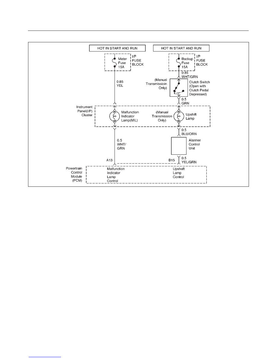
Upshift Lamp System Check (Manual Transmission Only)
D06RX063
Circuit Description
The shift lamp indicates the best transmission shift point
for maximum fuel economy.
The lamp is controlled by the Power Train Control Module
(PCM) and is turned “ON” by grounding the YEL/GRN
wire.
The PCM is used information from the following inputs to
control the upshift lamp.
f
Engine Coolant temperature (ECT) Sensor
f
Throttle Position Sensor
f
Vehicle Speed Sensor
f
Engine Speed
The PCM uses the measured RPM and the vehicle speed
to calculate what gear the vehicle is in.
It’s this calculation that determines when the upshift lamp
should be turned “ON”.
Diagnostic Aids
An intermittent may be caused by a poor connection,
rubbed-through wire insulation. Check for poor
connections or a damaged harness.
Inspect the PCM harness and connector for proper
mating, broken locks, improperly formed or damaged
terminals, poor terminal-to-wire connection and
damaged harness.
Test Description
1. This should not turn “ON” the up-shift lamp. If the
lamp is “ON”, there is a short to ground in YEL/GRN or
a fault PCM.
2. This checks the upshift lamp circuit up to the PCM
connector.
If the up-shift lamp illuminates, then the PCM
connector is faulty or PCM does not have the ability
to ground the circuit.

6E1–106
RODEO X22SE 2.2L ENGINE DRIVEABILITY AND EMISSION
Up-Shift Lamp System Check
Step
Action
Value(s)
Yes
No
1
1. Verify the customer complaints in accordance with
mentioned below: Go to the adequate Step Chart
first.
f
At the 1
st
gear position, the lamp doesn’t
illuminate: Go to Step Chart
f
At the 3
rd
gear position, the lamp doesn’t
illuminate: Go to Step Chart
f
Upshift Lamp doesn’t illuminate always.
2. Ignition “ON”, engine “OFF”.
3. Using the Tech 2, check to see if the upshift lamp
turn “ON” or “OFF”.
Does the upshift lamp stay “OFF”?
—
Go to
Step 2
Go to
Step 12
2
Check for an open of 15A Turn Backup Fuse.
Was a problem found?
—
Go to
Step 3
Go to
Step 4
Refer to Sec-
tion 8
3
Replace the fuse.
Is the action complete?
Verify Repair
—
—
4
Check for an burned out the Upshift Lamp.
Was a problem found?
—
Go to
Step 5
Go to
Step 6
5
Replace the Upshift Lamp.
Is the action complete?
Verify Repair
—
—
6
1. Check for an Clutch Switch operation and the fixing
condition.
2. Check for an open or short of clutch switch.
3. Check for an open or short of WHT/GRN wiring
harness between Turn Backup Fuse and Clutch
Switch.
Was a problem found?
—
Go to
Step 7
Go to
Step 8
7
1. Replace the Clutch Switch. Or,
2. Repair for an open or short of WHT/GRN wiring
harness.
Is the action complete?
Verify Repair
—
—
8
1. Check for an open or short of 1-2 Transmission
Switch.
2. Check for an open or short of 3-4 Transmission
Switch.
3. Check for an open or short of GRN wiring harness
between Clutch Switch and Transmission
Switches.
Was a problem found?
—
Go to
Step 9
Go to
Step 10
9
1. Replace the applicable Transmission Switch. or,
2. Repair for an open or short of GRN wiring harness.
Is the action complete?
Verify Repair
—
—
Нет комментариевНе стесняйтесь поделиться с нами вашим ценным мнением.
Текст