Isuzu Rodeo UE. Service manual — part 142
6A–57
ENGINE MECHANICAL (X22SE 2.2L)
NOTE: Do not apply engine oil to the bearing back faces.
6. Oil gallery, refer to “Crankshaft and Main Bearing” in
this manual.
7. Oil strainer and O-ring.
8. Install balance unit assembly, refer to “Balance Unit
Assembly: in this manual.
9. Install oil pan support assembly, refer to “Oil Pan and
Oil Pan Support” in this manual.
10. Install cylinder head gasket.
11. Install cylinder head assembly.
f
Refer to “Cylinder Head” in this manual.
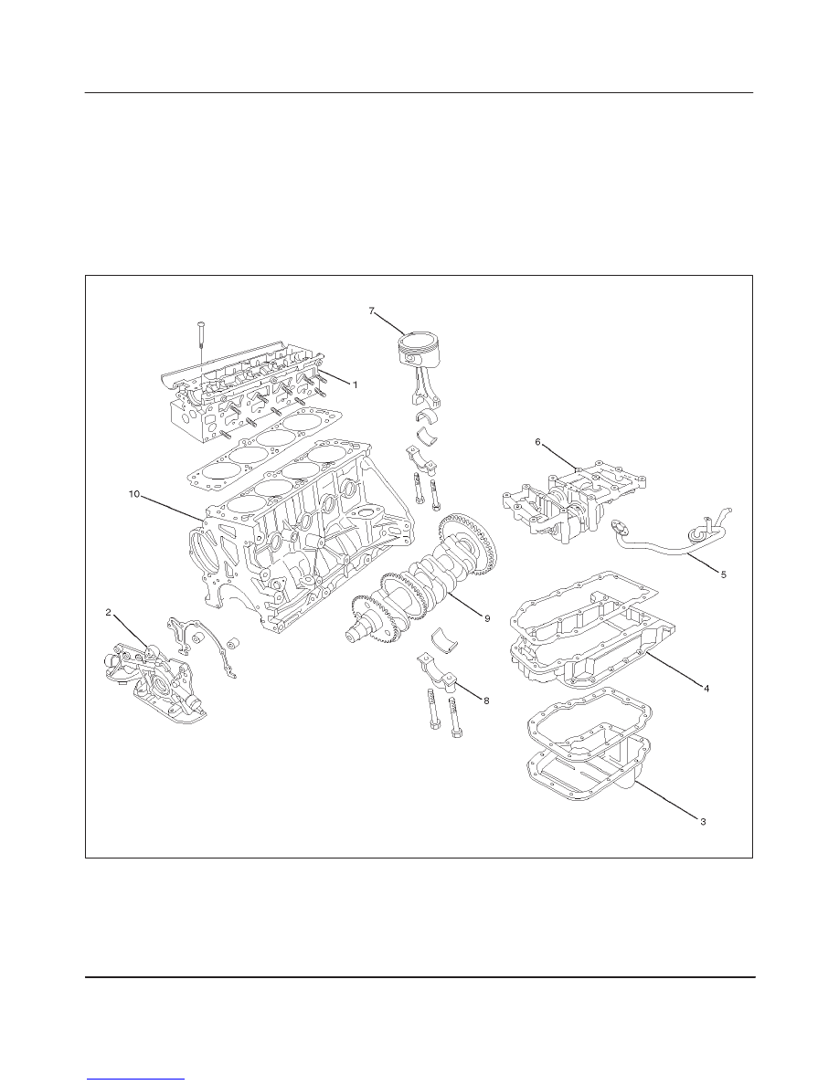
Cylinder Block
Cylinder Block and Associated Parts
015RW008
Legend
(1) Cylinder Head Assembly
(2) Oil Pump Assembly
(3) Oil Pan
(4) Oil Pan Support
(5) Oil Strainer
(6) Balance Unit Assembly
(7) Piston and Connecting Rod Assembly
(8) Main Bearing Cap
(9) Crankshaft
(10) Cylinder Block
6A–58
ENGINE MECHANICAL (X22SE 2.2L)
Disassembly
1. Remove cylinder head assembly.
2. Remove cylinder head gasket.
3. Remove oil pan assembly.
4. Remove oil pan support.
5. Remove oil strainer.
6. Remove oil pump assembly.
7. Remove balance unit assembly.
8. Remove piston and connecting rod assembly.
9. Remove flywheel.
10. Remove rear oil seal retainer assembly.
11. Remove main bearing cap.
12. Remove crankshaft.
13. Remove cylinder block.
Inspection and Repair
1. Remove the cylinder head gasket and any other
material adhering to the upper surface of the cylinder
block. Be very careful not to allow any material to
accidentally drop into the cylinder block. Be very
careful not to scratch the cylinder block.
2. Carefully remove the oil pump, rear oil seal retainer,
and crankcase assembly installation surface seal.
3. Wipe the cylinder block clean.
4. Visually inspect the cylinder block. If necessary, use a
flaw detector to perform a dye penetrate and
hydraulic (or air pressure) test. If cracking or other
damage is discovered, the cylinder block must either
be repaired or replaced.
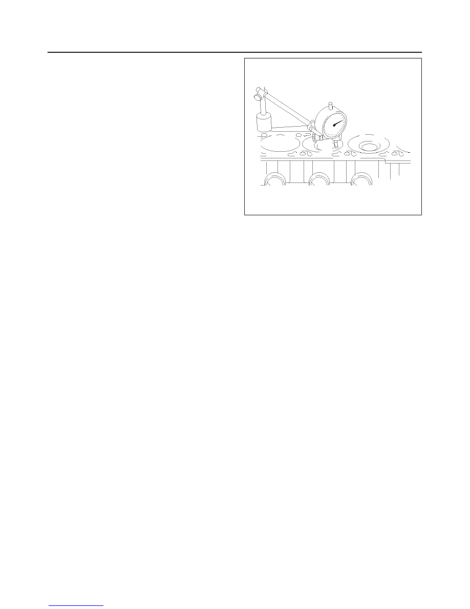
Flatness
1. Using a straight edge and feeler gauge, check that the
upper surface of the cylinder block is not warped.
CAUTION: Be very careful not to allow any material
to accidentally drop into the upper surface of the
cylinder block. Be very careful not to scratch the
upper surface of the cylinder block.
2. The cylinder block must be reground or replaced if the
warpage exceeds the limit.
Warpage
Limit : 0.40 mm (0.0156 in)
Maximum repairable limit: 0.40 mm (0.0156 in)
012RW013
Cylinder Bore
Use a cylinder gauge to measure the cylinder bore
diameter in both the axial and thrust directions. Each
measurement should be made at six points.
CAUTION: Be very careful not to allow any material
to accidentally drop into the upper surface of the
cylinder block. Be very careful not to scratch the
upper surface of the cylinder block.
If the measurement exceeds the specified limit, the
cylinder block must be replaced.
Diameter
Grade 1 : 85.975 mm–85.985 mm
(3.3530 in–3.3534 in)
Grade 2 : 85.985 mm–86.025 mm
(3.3534 in–3.3550 in)
Oversize : 0.5 mm (0.0195 in)
NOTE: For information on piston diameter, please refer
to the section “Inspection of the Piston and Connecting
Rod Assembly” in this manual.
6A–59
ENGINE MECHANICAL (X22SE 2.2L)
Reassembly
1. Install cylinder block.
2. Install crankshaft.
f
Install the main bearings to the cylinder block and
the main bearing caps.
f
Be sure that they are positioned correctly.
f
Apply new engine oil to the upper and lower main
bearing faces.
NOTE: Do not apply engine oil to the bearing back faces.
f
Carefully mount the crankshaft.
f
Apply engine oil to the thrust washer.
3. Install rear oil seal.
f
Coat lip of seal rings thinly with protective grease.
f
Install seal ring into cylinder block, use J–42616 (1)
and J–42613 (2).
015RW009
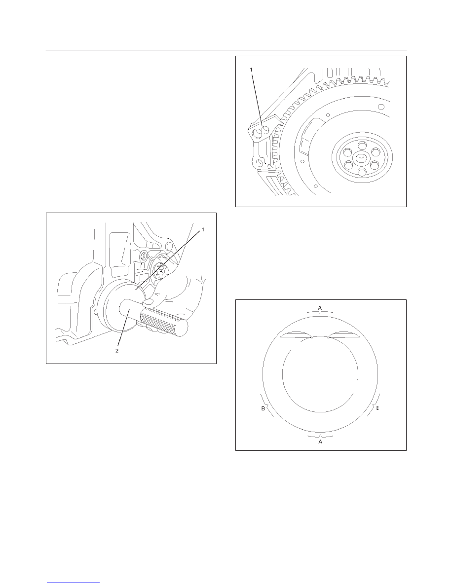
4. Install flywheel
1. Thoroughly clean and remove the oil from the
threads of crankshaft.
2. Remove the oil from the crankshaft and flywheel
mounting faces.
3. Mount the flywheel on the crankshaft and then
install the washer.
4. Use stopper (J–42618) to hold the crankshaft.
Prevent from rotating.
Tighten the flywheel bolts in 3 steps:
1st step: 65 N·m (48 lb ft)
2nd step: 30
°
3rd step: 15
°
NOTE: Do not reuse the bolt.
015RW010
5. Install piston and connecting rod assembly.
f
Apply engine oil to the cylinder bores, the
connecting rod bearings and the crankshaft pins.
NOTE: Do not apply engine oil to the bearing back faces.
f
Position ring gaps:
1 — Compression rings 180
°
to each other as
illustrated (A).
2 — Offset oil control rings 25 to 50 mm/1 to 2 in.
from gap of second compression ring (B).
015RW026
6. Install balance unit assembly and tighten the bolts in 2
steps in the order shown:
1st step : 20 N·m (14 lb ft)
2nd step : 45
°
7. Install oil pump assembly, refer to “Oil Pump” in this
manual.
8. Install oil strainer.
9. Install oil pan support.
10. Install oil pan assembly.
6A–60
ENGINE MECHANICAL (X22SE 2.2L)
1. Completely remove all residual sealant, lubricant
and moisture from the sealing surfaces. The
surfaces must be perfectly dry.
2. Apply a correct width bead of sealant (TB–1207C
or its equivalent) to the contact surfaces of the
crankcase. There must be no gaps in the bead.
3. The oil pan must be installed within 5 minutes
after sealant application.
4. Tighten the bolts and nuts to the specified torque
in 2 steps:
1st step : 8 N·m (5.8 lb ft)
2nd step : 30
°
11. Install cylinder head gasket.
12. Install cylinder head assembly, refer to “Cylinder
Head” in this manual.
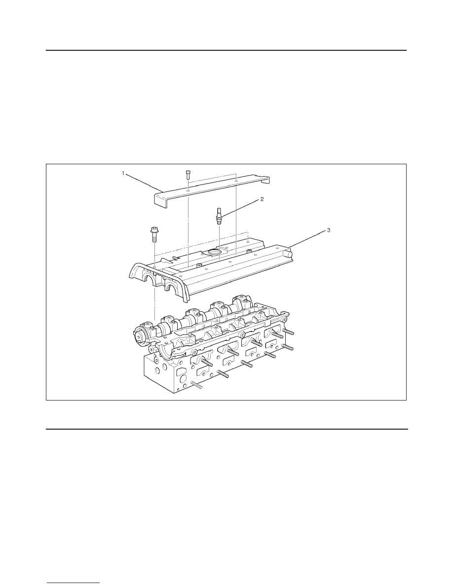
Cylinder Head Cover
Cylinder Head Cover and Associated parts
010RW004
Legend
(1) Ignition Cable Cover
(2) Spark Plug
(3) Cylinder Head Cover
Нет комментариевНе стесняйтесь поделиться с нами вашим ценным мнением.
Текст