Isuzu Rodeo UE. Service manual — part 262
6E1–419
RODEO X22SE 2.2L ENGINE DRIVEABILITY AND EMISSION
2. Inspect restriction for valve movement. If there is
restriction remove the object.
014RX056
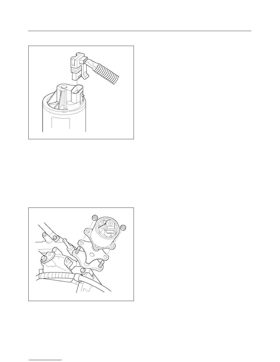
Installation Procedure
1. Place the gasket and EGR valve on to the intake
manifold.
2. Install mounting bolts and tighten.
3. Connect electrical connector at EGR valve
4. Connect the crankshaft breather hose and secure it
with clamps.
5. Install the air intake duct. Refer to Air Intake Duct
Installation Procedure.
6. Connect the negative battery cable.
014RX057
6E1–420
RODEO X22SE 2.2L ENGINE DRIVEABILITY AND EMISSION
Wiring and Connectors
Wiring Harness Service
The control module harness electrically connects the
control module to the various solenoids, switches and
sensors in the vehicle engine compartment and
passenger compartment.
Replace wire harnesses with the proper part number
replacement.
Because of the low amperage and voltage levels utilized
in powertrain control systems, it is essential that all wiring
in environmentally exposed areas be repaired with crimp
and seal splice sleeves.
The following wire harness repair information is intended
as a general guideline only. Refer to Chassis Electrical for
all wire harness repair procedures.
PCM Connectors And Terminals
Removal Procedure
1. Remove the connector terminal retainer.
2. Push the wire connected to the affected terminal
through the connector face so that the terminal is
exposed.
3. Service the terminal as necessary.
Installation Procedure
1. Bend the tab on the connector to allow the terminal to
be pulledinto position within the connector.
2. Pull carefully on the wire to install the connector
terminal retainer.
Connectors And Terminals
Connectors And Terminals
Use care when probing a connector and when replacing
terminals. It is possible to short between opposite
terminals. Damage to components could result. Always
use jumper wires between connectors for circuit
checking. NEVER probe through Weather–Pack seals.
Use an appropriate connector test adapter kit which
contains an assortment of flexible connectors used to
probe terminals during diagnosis. Use an appropriate
fuse remover and test tool for removing a fuse and to
adapt the fuse holder to a meter for diagnosis.
Open circuits are often difficult to locate by sight because
oxidation or terminal misalignment are hidden by the
connectors. Merely wiggling a connector on a sensor, or
in the wiring harness, may temporarily correct the open
circuit. Intermittent problems may also be caused by
oxidized or loose connections.
Be certain of the type of connector/terminal before
making any connector or terminal repair. Weather–Pack
and Com–Pack III terminals look similar, but are serviced
differently.
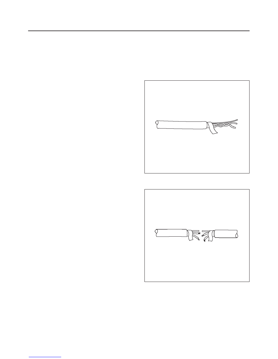
Wire Harness Repair: Twisted
Shielded Cable
Removal Procedure
1. Remove the outer jacket.
2. Unwrap the aluminum/mylar tape. Do not remove the
mylar.
047
3. Untwist the conductors.
4. Strip the insulation as necessary.
048
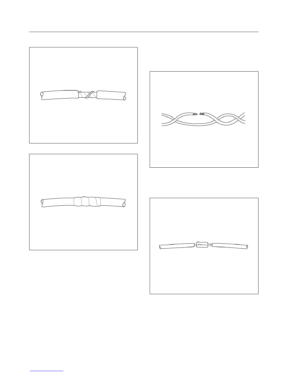
Installation Procedure
1. Splice the wires using splice clips and rosin core
solder.
2. Wrap each splice to insulate.
6E1–421
RODEO X22SE 2.2L ENGINE DRIVEABILITY AND EMISSION
3. Wrap the splice with mylar and with the drain
(uninsulated) wire.
049
4. Tape over the whole bundle to secure.
050
Twisted Leads
Removal Procedure
1. Locate the damaged wire.
2. Remove the insulation as required.
051
Installation Procedure
1. Use splice clips and rosin core solder in order to splice
the two wires together.
052
6E1–422
RODEO X22SE 2.2L ENGINE DRIVEABILITY AND EMISSION
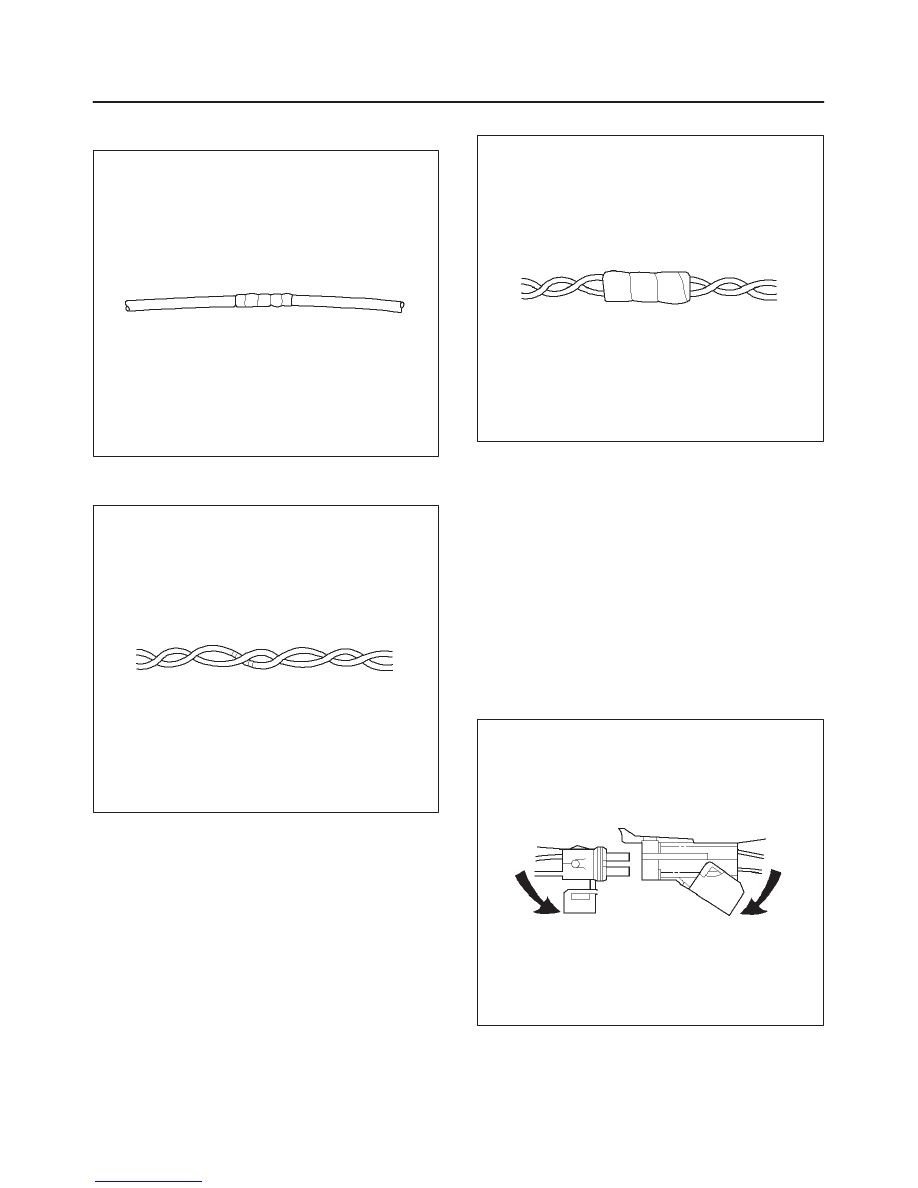
2. Cover the splice with tape in order to insulate it from
the other wires.
053
3. Twist the wires as they were before starting this
procedure.
054
4. Tape the wires with electrical tape.
055
Weather–Pack Connector
Tools Required
J 28742–A Weather–Pack II Terminal Remover
Removal Procedure
A Weather–Pack connector can be identified by a rubber
seal at the rear of the connector. This engine room
connector protects against moisture and dirt, which could
form oxidation and deposits on the terminals. This
protection is important, because of the low voltage and
the low amperage found in the electronic systems.
1. Open the secondary lock hinge on the connector.
070
Нет комментариевНе стесняйтесь поделиться с нами вашим ценным мнением.
Текст