Isuzu Rodeo UE. Service manual — part 42
FRONT SUSPENSION
3C–15
901RW159
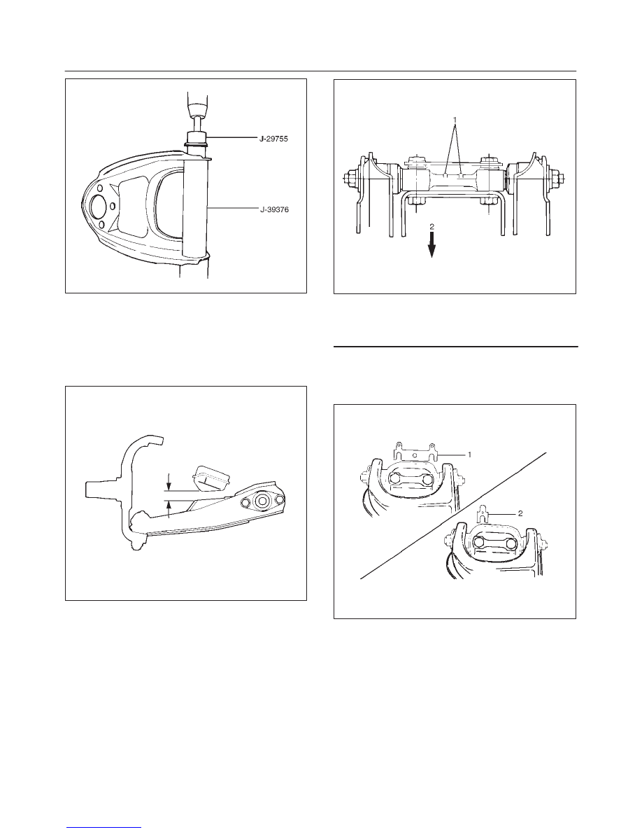
3. Install plate.
4. Install nut and tighten fulcrum pin nut finger–tight.
NOTE: Torque fulcrum pin nut after adjusting buffer
clearance.
Buffer clearance: 22 mm (0.87 in)
Torque: 108 N·m (80 lb ft)
450RS012
5. Install upper control arm assembly with the fulcrum
pin projections turned inward.
450RS013
Legend
(1) Projection
(2) Outward
6. Install the caster shims(2) between the chassis frame
and fulcrum pin.
7. Install the camber shims(1) between the chassis
frame and fulcrum pin.
450RS014
8. Install nut assembly.
9. Install bolt and plate, then tighten the bolt to the
specified torque.
Torque: 152 N·m (112 lb ft)
10. Install upper ball joint and tighten it to the specified
torque.
Torque: 57 N·m (42 lb ft)
11. Install nut and cotter pin then tighten the nut to the
specified torque, with just enough additional torque to
align cotter pin holes. Install new cotter pin.
Torque: 98 N·m (72 lb ft)
12. Install speed sensor cable.
3C–16
FRONT SUSPENSION
Lower Control Arm
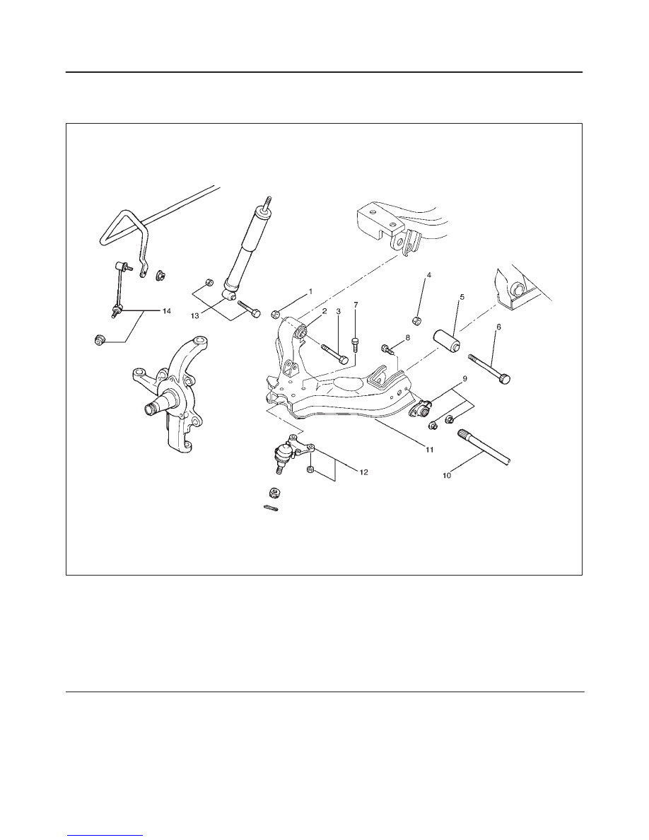
Lower Control Arm and Associated Parts
450RW010
Legend
(1) Nut, Front
(2) Bush, Front
(3) Bolt, Front
(4) Nut, Rear
(5) Bush, Rear
(6) Bolt, Rear
(7) Bolt, Lower Ball Joint
(8) Bolt, Torsion Bar Arm
(9) Torsion Bar Arm Bracket
(10) Torsion Bar
(11) Lower Control Arm
(12) Lower Ball Joint
(13) Shock Absorber
(14) Stabilizer Link
Removal
1. Raise the vehicle and support the frame with suitable
safety stands.
2. Remove wheel and tire assembly. Refer to Wheel in
this section.
3. Remove the tie-rod end from the knuckle. Refer to
Power Steering Unit in Steering section.
4. Remove the retaining ring from the front axle driving
shaft to release the shaft from hub(Except 2WD
model). Refer to Front Hub and Disc in Driveline/Axle
section.
5. Support lower control arm with a jack.
FRONT SUSPENSION
3C–17
6. Remove front nut.
7. Remove rear nut.
8. Remove torsion bar, refer to Torsion Bar in this
section.
9. Remove torsion bar arm bracket.
10. Disconnect the stabilizer link at the lower control arm.
11. Remove the shock absorber lower end from the lower
control arm.
12. Remove the lower ball joint from the lower control
arm.
13. Remove front bolt.
14. Remove rear bolt.
15. Remove lower control arm.
16. Remove torsion bar arm bolt.
17. Remove lower ball joint bolt.
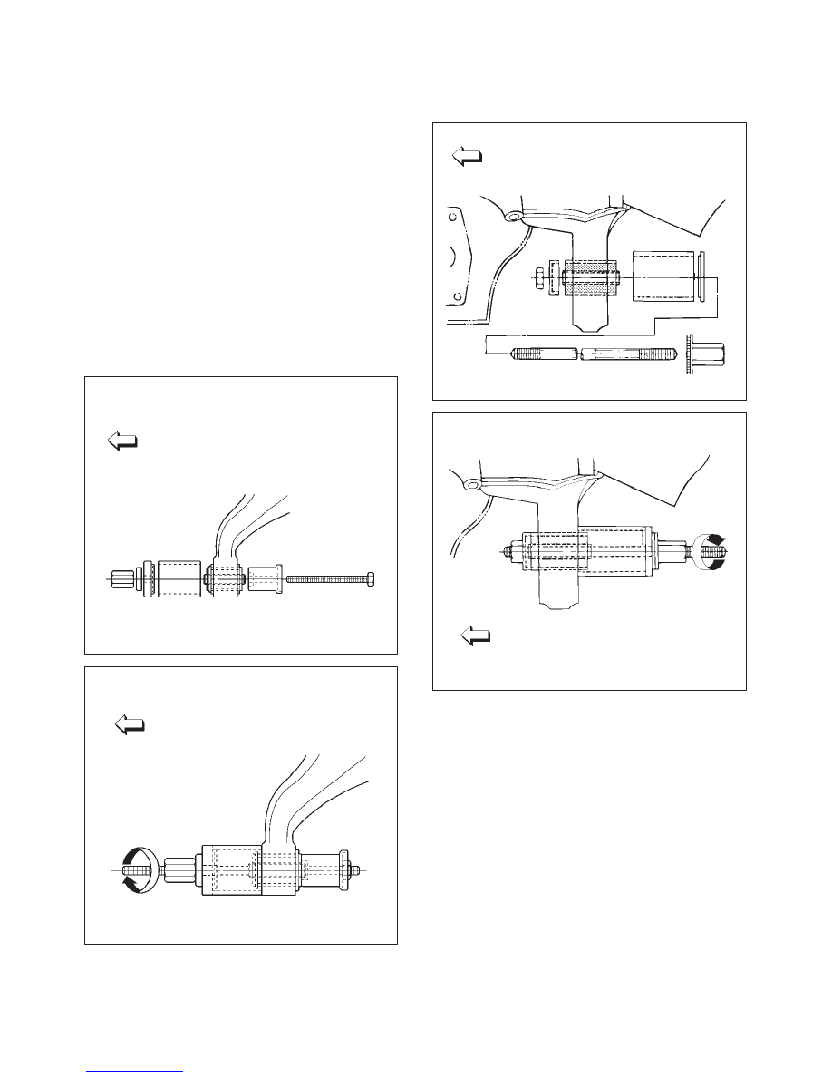
18. Remove front bushing by using remover J–36833.
901RW154
901RW155
19. Remove rear bushing by using remover J–36834.
901RW051
901RW052
Inspection and Repair
Make necessary correction or parts replacement if wear,
damage, corrosion or any other abnormal condition are
found through inspection.
Check the following parts:
f
Lower control arm
f
Bushing
3C–18
FRONT SUSPENSION
Installation
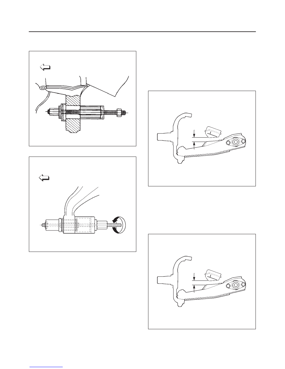
1. Install rear bushing by using installer J–36834.
901RW053
2. Install front bushing by using installer J–36833.
901RW156
3. Install lower ball joint bolt.
4. Install torsion bar arm bolt.
5. Install lower control arm.
6. Install rear bolt.
7. Install front bolt.
8. Install lower ball joint and tighten it to the specified
torque.
Torque: 116 N·m (85 lb ft)
9. Install shock absorber and tighten it to the specified
torque.
Torque: 93 N·m (69 lb ft)
10. Install stabilizer link and tighten it to the specified
torque.
Torque: 50 N·m (37 lb ft)
11. Install torsion bar arm bracket and tighten it to the
specified torque.
Torque: 116 N·m (85 lb ft)
12. Install Torsion bar, refer to Torsion Bar in this section.
13. Install rear nut and tighten lower link nut finger–tight.
NOTE: Torque lower control arm nut after adjusting buffer
clearance.
Buffer clearance: 22 mm (0.87 in)
Torque: 235 N·m (174 lb ft)
450RS012
14. Install front nut then tighten lower link nut finger-tight.
NOTE: Torque lower control arm nut after adjusting buffer
clearance .
Buffer clearance: 22 mm (0.87 in)
Torque: 190 N·m (140 lb ft)
NOTE: Adjust the trim height. Refer to Front End
Alignment Inspection and Adjustment in Steering section.
450RS012
Нет комментариевНе стесняйтесь поделиться с нами вашим ценным мнением.
Текст