Isuzu Rodeo UE. Service manual — part 281
6A–37
ENGINE MECHANICAL (6VD1 3.2L)
2. Install common chamber.
f
Refer to installation procedure for Common
Chamber in this manual.
3. Install cylinder head cover RH.
f
Refer to installation procedure for Cylinder Head
Cover RH in this manual.
4. Install cylinder head cover LH.
f
Refer to installation procedure for Cylinder Head
Cover LH in this manual.
5. Install timing belt.
f
Refer to installation procedure for Timing Belt in this
manual.
6. Install crankshaft pulley.
f
Refer to installation procedure for Crankshaft
Pulley in this manual.
7. Install Accelerator pedal cable.
6A–38
ENGINE MECHANICAL (6VD1 3.2L)
Valve Stem Oil Controller , Valve Spring and Valve Guide
Removal
1. Disconnect battery ground cable.
2. Drain engine oil.
f
Drain engine coolant.
3. Remove cylinder head assembly.
f
Refer to removal procedure for Cylinder Head in
this manual.
4. Remove camshaft.
f
Refer to removal procedure for Camshaft in this
manual.
5. Remove tappets with shim.
NOTE: Do not damage shim surface.
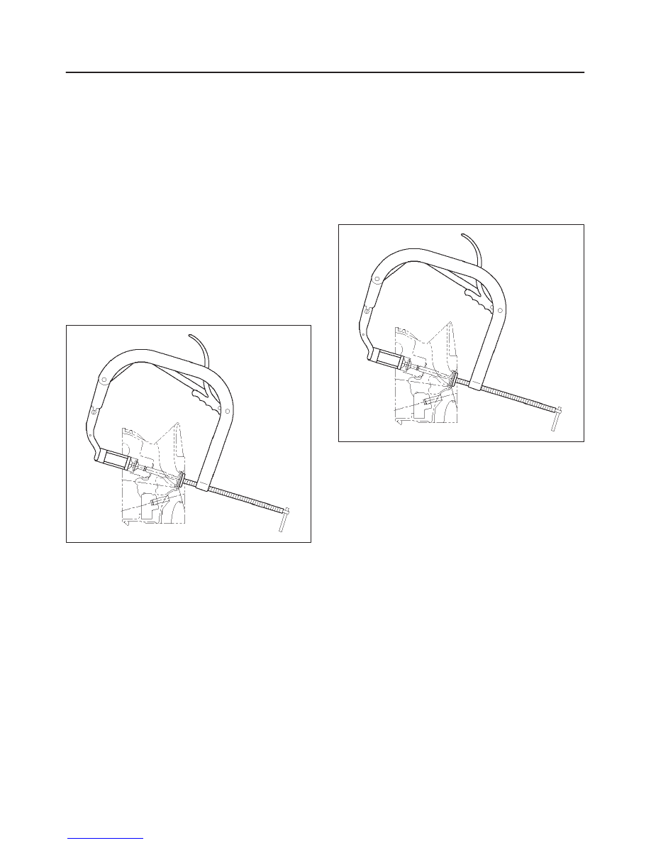
6. Remove valve springs using J-8062 valve spring
compressor and J-42898 valve spring compressor
adapter then remove upper valve spring seat and
lower seat.
014RW042
7. Remove oil controller using J-37281 oil controller
remover, remove each valve stem oil controller.
8. Remove valve guide using J-37985 valve guide
replacer.
Installation
1. Install valve guide using J-42899 valve guide installer.
2. Install oil controller using J-38537 oil controller
installer.
3. Install lower valve spring seat, valve spring and upper
valve spring seat then put split collars on the upper
spring seat, using J-8062 valve spring compressor
and J-42898 valve spring compressor adapter to
install the split collars.
014RW042
4. Install tappet with shim.
5. Install camshaft assembly.
f
Refer to installation procedure for Camshaft in this
manual.
6. Install cylinder head assembly.
f
Refer to installation procedure for Cylinder Head in
this manual.
7. Fill engine oil until full level.
8. Fill engine coolant.
6A–39
ENGINE MECHANICAL (6VD1 3.2L)
Piston, Piston Ring and Connecting Rod
Removal
F06RW011
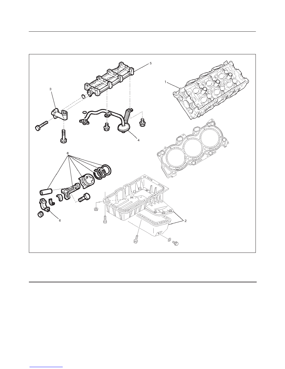
Legend
(1) Cylinder Head
(2) Crankcase with Oil Pan
(3) Oil Pipe
(4) Oil Strainer
(5) Oil Gallery
(6) Piston with Connecting Rod Assembly
1. Remove cylinder head assembly.
f
Refer to removal procedure for Cylinder Head in
this manual.
2. Remove crankcase with oil pan.
f
Refer to removal procedure for Oil Pan and
Crankcase in this manual.
6A–40
ENGINE MECHANICAL (6VD1 3.2L)
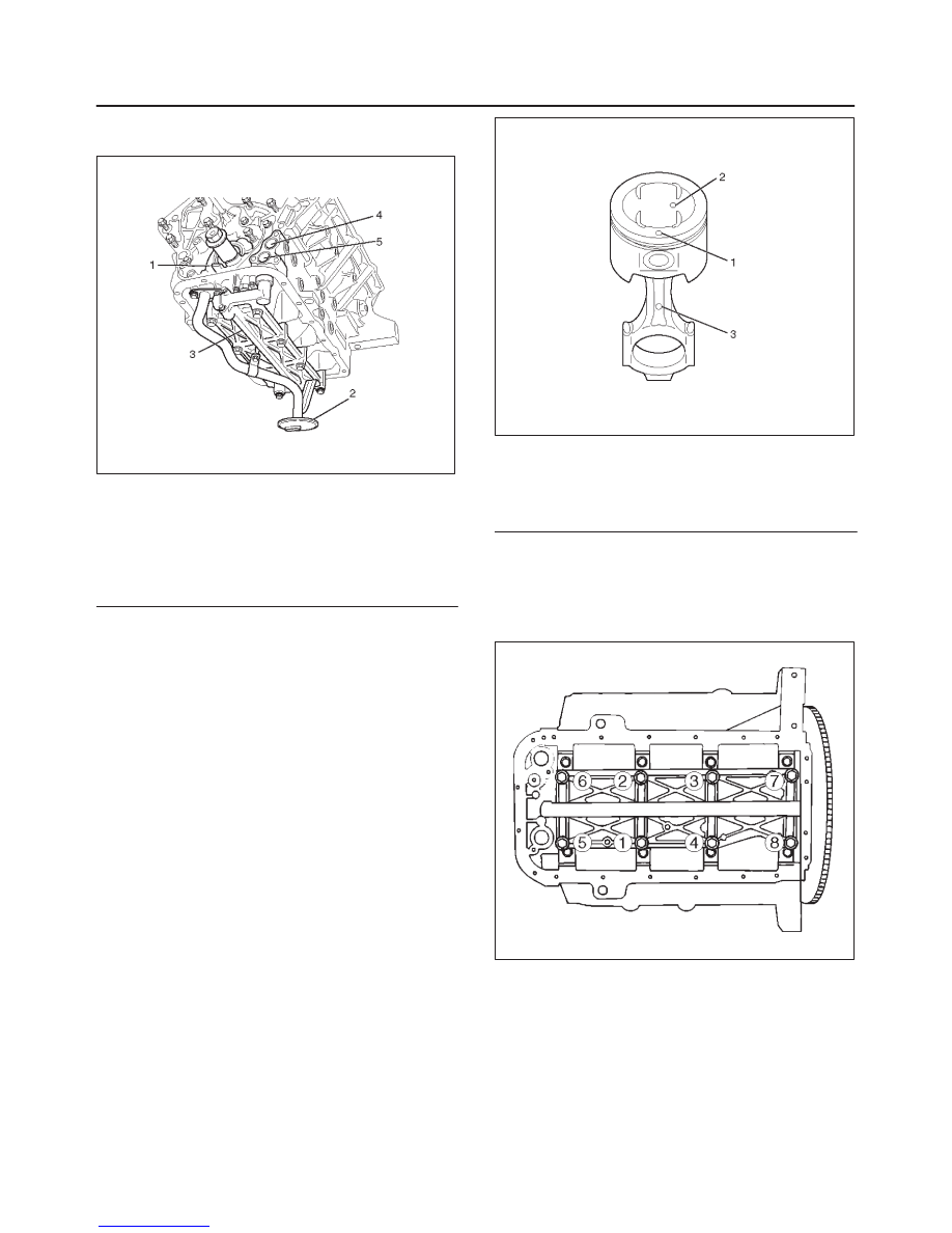
3. Remove oil strainer fixing bolts, remove oil strainer
assembly with O-ring.
050RW002
Legend
(1) Oil Pump
(2) Oil Strainer
(3) Oil Gallery
(4) From Oil Filter
(5) To Oil Filter
4. Remove three fixing bolts, oil pipe with O-ring.
5. Remove eight fixing bolts, oil gallery.
6. Remove piston with connecting rod assembly, before
removing the bearing cap, remove carbon on the top
of cylinder bore and push piston with connecting rod
out from the top of cylinder bore.
Installation
1. Install piston with connecting rod assembly.
f
Apply engine oil to cylinder bore, connecting rod
bearing and crank pin.
When installing the piston, its front mark must face
the engine front side.
f
The bearing cap number must be the same as
connecting rod number.
f
Apply engine oil to the thread and seating surface of
each nut.
f
Tighten nuts to the specified torque.
Torque : 54 N·m (40 lb ft)
f
After tightening the nuts, make sure that the
crankshaft rotates smoothly.
NOTE: Do not apply engine oil to the bearing back faces
and connecting rod bearing fitting surfaces.
015RW003
Legend
(1) Piston Front Mark
(2) Piston Grade
(3) Connecting Rod Front Mark
2. Install oil gallery and tighten the bolts in two steps, in
the order shown in illustration.
Torque :
1st step : 29 N·m (21 lb ft)
2nd step : 55
°
–65
°
051RS009
3. Install oil pipe with O-ring.
Torque : 10 N·m (89 lb in)
4. Install oil strainer assembly with O-ring.
Torque : 25 N·m (18 lb ft)
5. Install crankcase with oil pan.
f
Refer to installation procedure for Oil Pan and
Crankcase in this manual.
6. Install cylinder head assembly.
f
Refer to installation procedure for Cylinder Head in
this manual.
Нет комментариевНе стесняйтесь поделиться с нами вашим ценным мнением.
Текст