Isuzu Rodeo UE. Service manual — part 29
2A–12 POWER–ASSISTED STEERING SYSTEM
4. Install all the lines and hoses. Fill the system with new
power steering fluid and bleed the system as
described in Bleeding The Power Steering System.
Operate the engine for about 15 minutes.
Remove the pump return line at the pump inlet and
plug the connection on the pump. While refilling the
reservoir, check the draining fluid for contamination.
If foreign material is still evident, replace all lines,
disassemble and clean or replace the power steering
system components. Do not re-use any drained
power steering fluid.
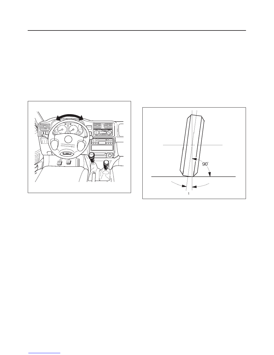
Steering Wheel Free Play Inspection
430RX003
1. With the tires in the straight-ahead position, check the
amount of steering wheel play by turning the wheel in
both directions until the tires begin to move.
NOTE: The wheel free play should be checked with the
engine running.
Free play: 0 – 30 mm (0 – 1.18 in)
2. Also check the steering wheel for play and looseness
in the mount by moving it back and forth and
sideways. When test driving, check for hard steering,
steering shimmy and tendency to pull to one side.
Front End Alignment Inspection and
Adjustment
General Description
“Front End Alignment” refers to the angular relationship
between the front wheels, the front suspension attaching
parts and the ground.
Proper front end alignment must be maintained in order to
insure efficient steering, good directional stability and to
prevent abnormal tire wear.
The most important factors of front end alignment are
wheel toe-in, wheel camber and axle caster.
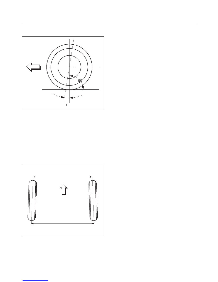
Camber:
This illustration shows view from the front of the vehicle.
480RS004
Camber is the vertical tilting inward or outward of the front
wheels. When the wheels tilt outward at the top, the
camber is positive (+). When the wheels tilt inward at the
top, the camber is negative (-). The amount of tilt
measured in degrees from the vertical is called the
camber angle (1). If camber is extreme or unequal
between the wheels, improper steering and excessive tire
wear will result. Negative camber causes wear on the
inside of the tire, while positive camber causes wear to the
outside.
POWER–ASSISTED STEERING SYSTEM
2A–13
Caster:
This illustration shows view from the side of the vehicle.
480RS005
Caster (1) is the vertical tilting of the wheel axis either
forward or backward (when viewed from the side of the
vehicle). A backward tilt is positive (+) and a forward tilt is
negative (-). On the short and long arm type suspension
you cannot see a caster angle without a special
instrument, but if you look straight down from the top of
the upper control arm to the ground, the ball joints do not
line up (fore and aft) when a caster angle other than 0
degree is present. With a positive angle, the lower ball
joint would be slightly ahead (toward the front of the
vehicle) of the upper ball joint center line.
Toe-in:
This illustration shows view from the top of the vehicle.
480RS003
Toe-in is the measured amount the front wheels are turn
in. The actual amount of toe-in is normally a fraction of a
degree. Toe-in is measured from the center of the tire
treads or from the inside of the tires. The purpose of
toe-in is to insure parallel rolling of the front wheels and to
offset any small deflections of the wheel support system
which occurs when the vehicle is rolling forward.
Incorrect toe-in results in excessive toe-in and unstable
steering. Toe-in is the last alignment to be set in the front
end alignment procedure.
Inspection
Before making any adjustments affecting caster, camber
or toe-in, the following front end inspection should be
made.
1. Inspect the tires for proper inflation pressure. Refer to
Main Data and Specifications in Wheel and Tire
System section.
2. Make sure that the vehicle is unladen condition (With
no passenger or loading).
3. Make sure that the spare tire is installed at the normal
position.
4. Inspect the front wheel bearings for proper
adjustment. Refer to Front Hub and Disc Overhaul in
Suspension section.
5. Inspect the ball joints and tie rod ends. If excessive
looseness is noted, correct before adjusting. Refer to
Steering Linkage in this section.
6. Inspect the wheel and tires for run-out. Refer to
Wheel Replacement in Wheel and Tire System
section.
7. Inspect the trim height. If not within specifications,
the correction must be made before adjusting caster.
8. Inspect the steering unit for looseness at the frame.
9. Inspect shock absorbers for leaks or any noticeable
noise. Refer to Shock Absorber in Suspension
section.
10. Inspect the control arms or stabilizer bar attachment
for looseness. Refer to Suspension section .
11. Inspect the front end alignment using alignment
equipment. Follow the manufacturer’s instructions.
12. Park the vehicle must be on a level surface.
2A–14 POWER–ASSISTED STEERING SYSTEM
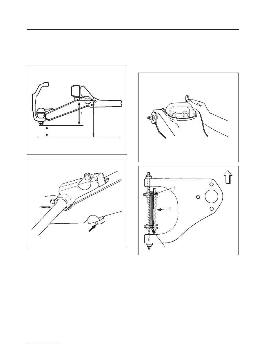
Trim Height Adjustment
Adjust the trim height (1) by means of the adjusting bolt on
the height control arms.
CAUTION: When adjusting front end alignment, be
sure to begin with trim height first, as it may change
other adjusted alignments.
450RS003
410RS001
1. Check and adjust the tire inflation pressures.
2. Park the vehicle on a level ground and move the front
of the vehicle up and down several times to settle the
suspension.
3. Make necessary adjustment with the adjusting bolt on
the height control arms.
Trim height: 119
±
5 mm (4.69
±
0.2 in)
Caster Adjustment
The caster angle can be adjusted by means of the caster
shims (1) installed between the chassis frame (2) and
fulcrum pins.
Caster angle: 2
°
30’
±
1
°
CAUTION: Left and right side must be equal within
30’.
450RW006
450RS002
NOTE: Difference of the caster shim front/rear thickness
should be 3.6 mm (0.142 in) or less. Overall thickness of
caster shim and camber shim should be 10.8 mm
(0.425 in) or less.
Tighten the fulcrum pin bolt to the specified torque.
Torque: 152 N·m 112 ( lb ft)
POWER–ASSISTED STEERING SYSTEM
2A–15
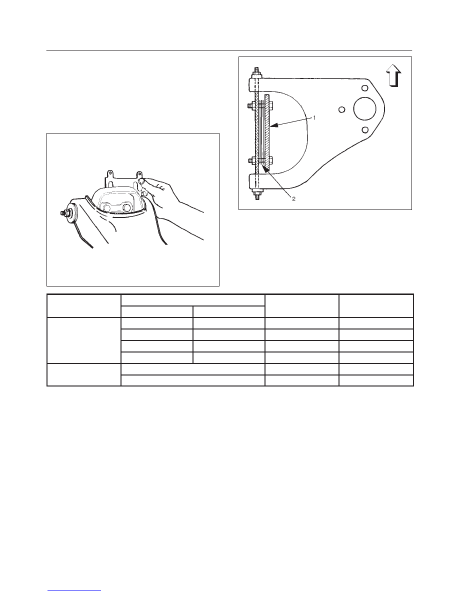
Camber Adjustment
The camber angle can be adjusted by means of the
camber shims (2) installed in position between the
chassis frame (1) and fulcrum pins
Camber angle: 0
°
±
30’
King pin inclination: 12
°
30’
±
30’
CAUTION: Left and right side must be equal within
30’.
450RW007
450RS005
NOTE: Overall thickness of caster shim and camber
shim should be 10.8 mm (0.425 in) or less.
Tighten the fulcrum pin bolt to the specified torque.
Torque: 152 N·m (112 lb ft)
Position of shims
Camber angle
Caster angle
Front side
Rear side
Camber angle
Caster angle
When added
When removed
Decreases
Decreases
Caster shim
When removed
When added
Increases
Increases
Caster shim
—
When removed
Unchanged
Decreases
—
When added
Unchanged
Increases
Camber shim
When added
Decreases
Unchanged
Camber shim
When removed
Increases
Unchanged
Нет комментариевНе стесняйтесь поделиться с нами вашим ценным мнением.
Текст