Isuzu Rodeo UE. Service manual — part 161
6E1–15
RODEO X22SE 2.2L ENGINE DRIVEABILITY AND EMISSION
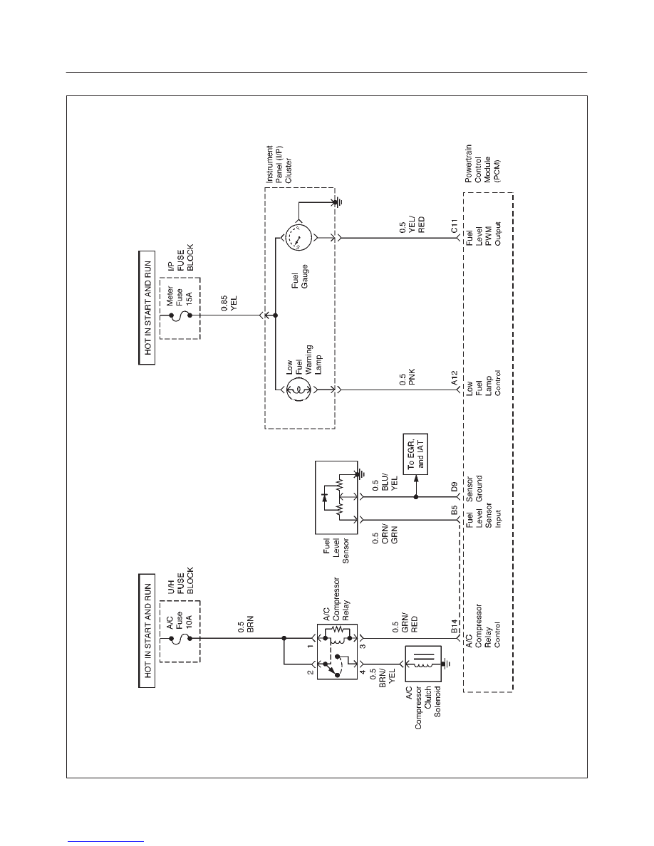
PCM WIRING DIAGRAM (9 of 10)
D06RX034
6E1–16
RODEO X22SE 2.2L ENGINE DRIVEABILITY AND EMISSION
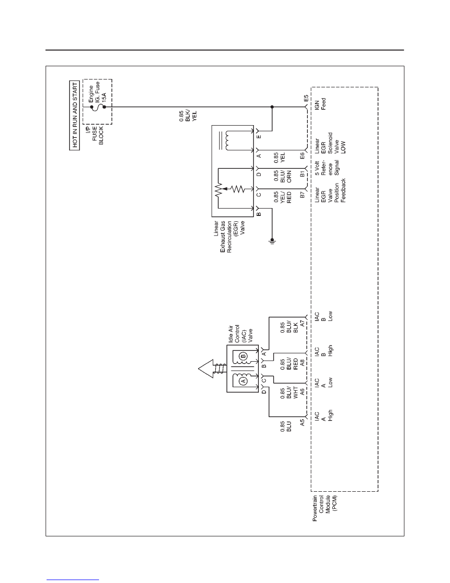
PCM WIRING DIAGRAM (10 of 10)
D06RX035
6E1–17
RODEO X22SE 2.2L ENGINE DRIVEABILITY AND EMISSION
PCM PINOUTS
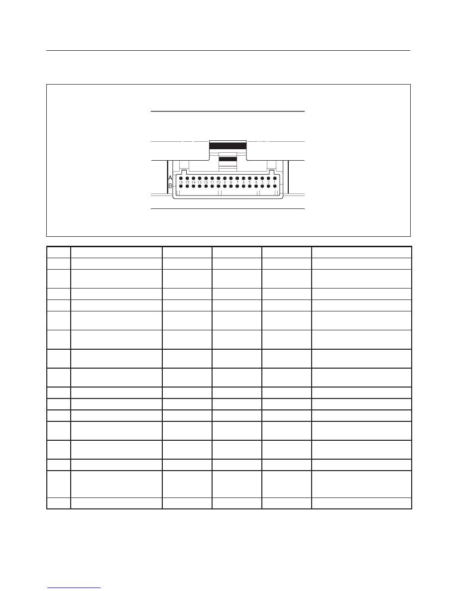
PCM Pinout Table, 32–Pin Red Connector – Row ”A”
TS23344
PIN
PIN Function
Wire Color
IGN ON
ENG RUN
Refer To
A1
5 Volt Reference Signal
RED
5.0 V
5.0 V
Appropriate Sensor
A2
Knock Sensor Input
YEL
—
3.0 V (MAX)
General Description and
Operation, Knock Sensor
A3
Not Used
—
A4
Battery Feed
RED/WHT
B+
B+
Chassis Electrical
A5
Idle Air Control (IAC) ”A”
High
BLU
B+/0.8 V
B+/0.8 V
General Description and
Operation, IAC
A6
IAC ”A” Low
BLU/WHT
B+/0.8 V
B+/0.8 V
General Description and
Operation, IAC
A7
IAC ”B” Low
BLU/BLK
B+/0.8 V
B+/0.8 V
General Description and
Operation, IAC
A8
IAC ”B” High
BLU/RED
B+/0.8 V
B+/0.8 V
General Description and
Operation, IAC
A9
Not Used
—
—
—
—
A10
Not Used
—
—
—
—
A11
Not Used
—
—
—
—
A12
Low Fuel Warning Lamp
Control
PNK
0.4–0.9 V
B+
Chassis Electrical
A13
Malfunction Indicator
Lamp (MIL) Control
WHT/GRN
0.4–0.9 V
B+
Chassis Electrical
A14
Rear Defogger Relay
RED/WHT
B+
B+
Classis Electrical
A15
EVAP Canister Vent
Solenoid Control
RED/BLU
B+
0–5 V
(varies)
General Description and
Operation, EVAP Emission
Control System
A16
Not Used
—
—
—
—
6E1–18
RODEO X22SE 2.2L ENGINE DRIVEABILITY AND EMISSION
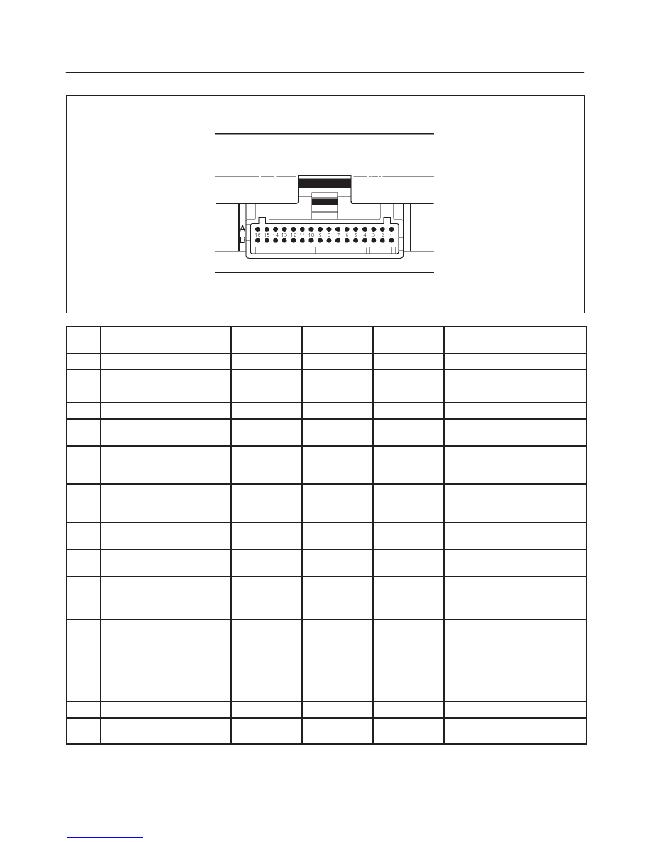
PCM Pinout Table, 32–Pin Red Connector – Row ”B”
TS23344
PIN
PIN Function
Wire Color
IGN ON
ENG RUN
Refer To
B1
5 Volt Reference Signal
BLU/ORG
5.0 V
5.0 V
Appropriate Sensor
B2
Not Used
—
—
—
—
B3
Not Used
—
—
—
—
B4
Not Used
—
—
—
—
B5
Fuel Tank Level Sensor
ORN/GRN
—
—
General Description and
Operation, Fuel Pump
B6
Fuel Tank Vapor Pressure
Sensor Input
GRY
0.2 to 4.9 V
(0.5V = +5in
H2O)
0.2 to 4.9 V
(4.5V = –15
in H2O)
General Description and
Operation, Fuel Pump
B7
Exhaust Gas Recirculation
(EGR) Position Feedback
YEL/RED
0.6 V
0.6 V
General Description and
Operation, Linear EGR
Control
B8
Intake Air Temperature
(IAT) Sensor
YEL/GRN
~3V
(0V = 151
°
C)
~3 V
(5V = –40
°
C)
General Description and
Operation, IAT
B9
A/C Pressure Sensor
Signal
GRN
~1 V
~1 V
A/C System
B10
Not Used
—
—
—
—
B11
Power Steering Pressure
(PSP) Switch Input
GRN/YEL
B+
B+
General Description and
Operation, PSP
B12
Illumination Switch
GRN/YEL
B+
B+
Chassis Electrical
B13
Class 2 Data
ORN/BLK
0.0 V
0.0 V
Diagnosis, Class 2 Serial
Data
B14
A/C Compressor Clutch
Relay Control Compressor
GRN/RED
0
(A/C OFF)
B+
(A/C ON)
General Description and
Operation, A/C Clutch Circuit
Operation
B15
Upshift Lamp Control
YEL/GRN
—
—
—
B16
EVAP Canister Purge
Valve Solenoid
BRN/WHT
—
—
General Description and
Operation, EVAP
Нет комментариевНе стесняйтесь поделиться с нами вашим ценным мнением.
Текст