Isuzu Rodeo UE. Service manual — part 38
2A–48 POWER–ASSISTED STEERING SYSTEM
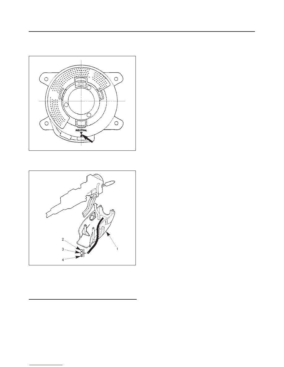
CAUTION: When turning the SRS coil counter
clockwise to full, stop turning if resistance is felt.
Forced further turning may damage to the cable in
the SRS coil.
825RW016
12. When installing the steering column cover, be sure to
route each wire harness as illustrated so that the
harnesses do not catch any moving parts.
825RW017
Legend
(1) Steering Column Cover
(2) Starter Switch Harness
(3) Combination Switch Harness
(4) Inflator Module Harness
13. Install steering wheel and align the setting marks
made when removing.
CAUTION: Never apply force to the steering wheel
in direction of the shaft by using a hammer or other
impact tools in an attempt to remove the steering
wheel. The steering shaft is designed as an energy
absorbing unit.
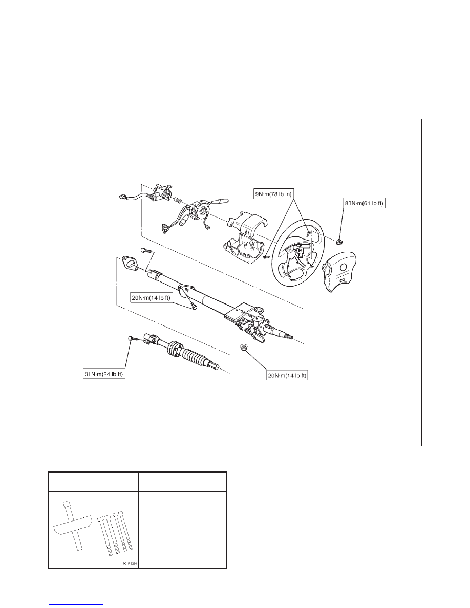
14. Tighten the steering wheel fixing nut to the specified
torque.
Torque: 34 N·m (25 lb ft)
15. Support the module and carefully connect the module
connector and horn lead, then install inflator module.
NOTE: Pass the lead wire through the tabs on the plastic
cover (wire protector) of inflator to prevent lead wire from
being pinched.
16. Tighten bolts to specified torque.
Torque: 9 N·m (78 lb in)
17. Install driver knee bolster (reinforcement).
18. Install instrument panel lower cover.
19. Install the engine hood opening lever.
20. Connect the yellow 2-way SRS connector and horn
lead located under the steering column.
21. Connect the battery “–” terminal cable.
System Inspection
Turn the ignition switch to “ON” while watching warning
light.
The light should flash 7 times and then go off. If lamp does
not operate correctly, refer to Restraints section.
POWER–ASSISTED STEERING SYSTEM
2A–49
Supplemental Restraint System Steering Wheel & Column and
Associated Parts
Main Data and Specifications
Torque Specifications
E02RX003
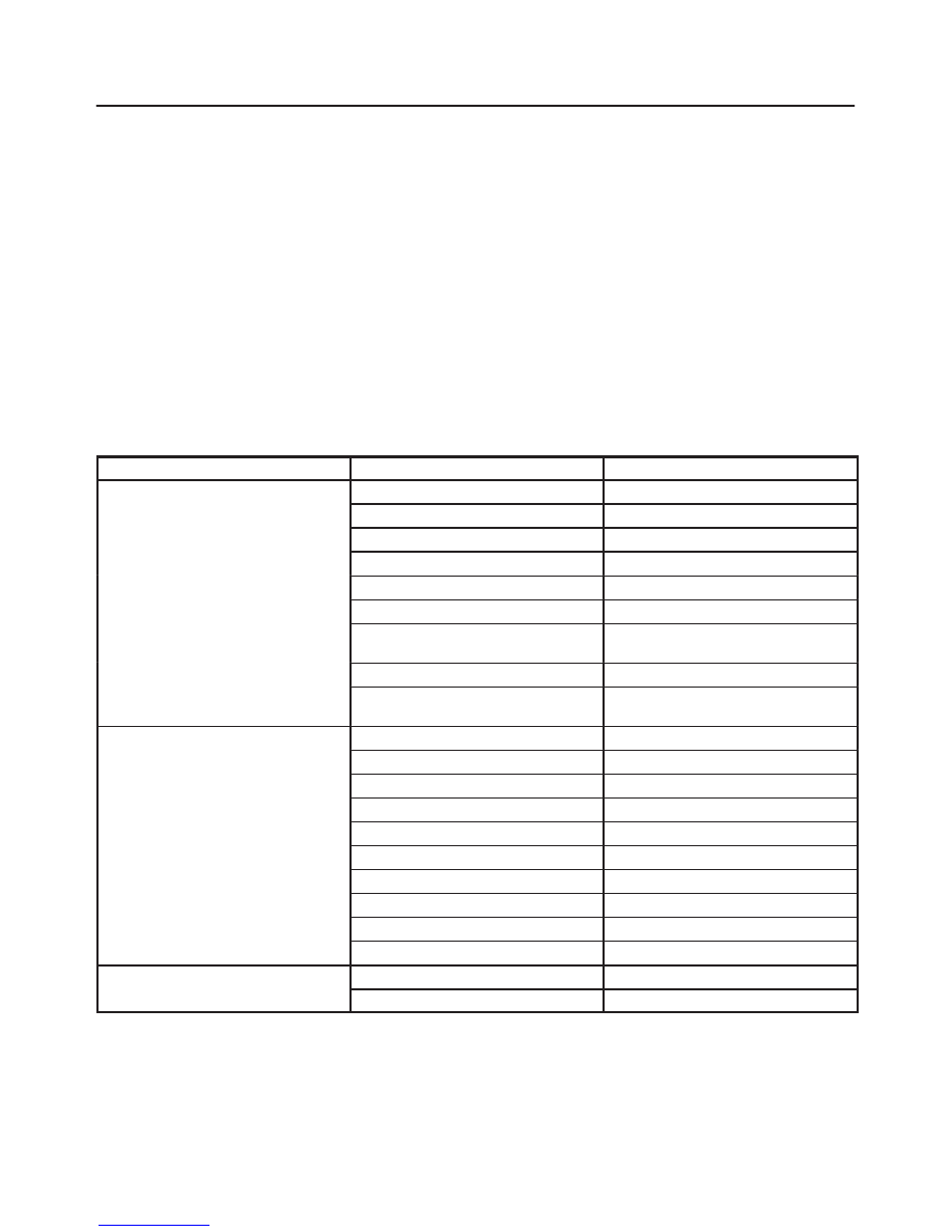
Special Tools
ILLUSTRATION
TOOL NO.
TOOL NAME
J–29752
Steering wheel remover
FRONT SUSPENSION
3C–1
RODEO
SUSPENSION
CONTENTS
Front Suspension
3C–1
. . . . . . . . . . . . . . . . . . . . . . .
Rear Suspension
3D–1
. . . . . . . . . . . . . . . . . . . . . . . .
Wheel and Tire System
3E–1
. . . . . . . . . . . . . . . . . .
FRONT SUSPENSION
CONTENTS
Service Precaution
3C–1
. . . . . . . . . . . . . . . . . . . . . .
General Description
3C–2
. . . . . . . . . . . . . . . . . . . . .
Diagnosis
3C–2
. . . . . . . . . . . . . . . . . . . . . . . . . . . . . .
Shock Absorber
3C–5
. . . . . . . . . . . . . . . . . . . . . . . . .
Shock Absorber and Associated Parts
3C–5
. . . .
Removal
3C–5
. . . . . . . . . . . . . . . . . . . . . . . . . . . . .
Inspection and Repair
3C–5
. . . . . . . . . . . . . . . . . .
Installation
3C–5
. . . . . . . . . . . . . . . . . . . . . . . . . . . .
Stabilizer Bar
3C–6
. . . . . . . . . . . . . . . . . . . . . . . . . . .
Stabilizer Bar and Associated Parts
3C–6
. . . . . .
Removal
3C–6
. . . . . . . . . . . . . . . . . . . . . . . . . . . . .
Inspection and Repair
3C–6
. . . . . . . . . . . . . . . . . .
Installation
3C–6
. . . . . . . . . . . . . . . . . . . . . . . . . . . .
Torsion Bar
3C–7
. . . . . . . . . . . . . . . . . . . . . . . . . . . . .
Torsion Bar and Associated Parts
3C–7
. . . . . . . .
Removal
3C–7
. . . . . . . . . . . . . . . . . . . . . . . . . . . . .
Inspection and Repair
3C–8
. . . . . . . . . . . . . . . . . .
Installation
3C–8
. . . . . . . . . . . . . . . . . . . . . . . . . . . .
Knuckle
3C–10
. . . . . . . . . . . . . . . . . . . . . . . . . . . . . . . .
Knuckle and Associated Parts
3C–10
. . . . . . . . . . .
Removal
3C–10
. . . . . . . . . . . . . . . . . . . . . . . . . . . . .
Inspection and Repair
3C–11
. . . . . . . . . . . . . . . . . .
Installation
3C–11
. . . . . . . . . . . . . . . . . . . . . . . . . . . .
Upper Control Arm
3C–13
. . . . . . . . . . . . . . . . . . . . . .
Upper Control Arm and Associated Parts
3C–13
.
Removal
3C–13
. . . . . . . . . . . . . . . . . . . . . . . . . . . . .
Inspection and Repair
3C–14
. . . . . . . . . . . . . . . . . .
Installation
3C–14
. . . . . . . . . . . . . . . . . . . . . . . . . . . .
Lower Control Arm
3C–16
. . . . . . . . . . . . . . . . . . . . . .
Lower Control Arm and Associated Parts
3C–16
.
Removal
3C–16
. . . . . . . . . . . . . . . . . . . . . . . . . . . . .
Inspection and Repair
3C–17
. . . . . . . . . . . . . . . . . .
Installation
3C–18
. . . . . . . . . . . . . . . . . . . . . . . . . . . .
Upper Ball Joint
3C–19
. . . . . . . . . . . . . . . . . . . . . . . . .
Upper Ball Joint and Associated Parts
3C–19
. . . .
Removal
3C–19
. . . . . . . . . . . . . . . . . . . . . . . . . . . . .
Inspection and Repair
3C–20
. . . . . . . . . . . . . . . . . .
Installation
3C–20
. . . . . . . . . . . . . . . . . . . . . . . . . . . .
Lower Ball Joint
3C–21
. . . . . . . . . . . . . . . . . . . . . . . . .
Lower Ball Joint and Associated Parts
3C–21
. . . .
Removal
3C–21
. . . . . . . . . . . . . . . . . . . . . . . . . . . . .
Inspection and Repair
3C–22
. . . . . . . . . . . . . . . . . .
Installation
3C–22
. . . . . . . . . . . . . . . . . . . . . . . . . . . .
Main Data and Specifications
3C–23
. . . . . . . . . . . . .
Special Tools
3C–24
. . . . . . . . . . . . . . . . . . . . . . . . . . .
Service Precaution
WARNING: THIS VEHICLE HAS A SUPPLEMENTAL
RESTRAINT SYSTEM (SRS). REFER TO THE SRS
COMPONENT AND WIRING LOCATION VIEW IN
ORDER TO DETERMINE WHETHER YOU ARE
PERFORMING SERVICE ON OR NEAR THE SRS
COMPONENTS OR THE SRS WIRING. WHEN YOU
ARE PERFORMING SERVICE ON OR NEAR THE SRS
COMPONENTS OR THE SRS WIRING, REFER TO
THE SRS SERVICE INFORMATION. FAILURE TO
FOLLOW WARNINGS COULD RESULT IN POSSIBLE
AIR BAG DEPLOYMENT, PERSONAL INJURY, OR
OTHERWISE UNNEEDED SRS SYSTEM REPAIRS.
CAUTION: Always use the correct fastener in the
proper location. When you replace a fastener, use
ONLY the exact part number for that application.
ISUZU will call out those fasteners that require a
replacement after removal. ISUZU will also call out
the fasteners that require thread lockers or thread
sealant. UNLESS OTHERWISE SPECIFIED, do not
use supplemental coatings (Paints, greases, or other
corrosion inhibitors) on threaded fasteners or
fastener joint interfaces. Generally, such coatings
adversely affect the fastener torque and the joint
clamping force, and may damage the fastener. When
you install fasteners, use the correct tightening
sequence and specifications. Following these
instructions can help you avoid damage to parts and
systems.
3C–2
FRONT SUSPENSION
General Description
The front suspension is designed to allow each wheel to
compensate for changes in the road surface level without
greatly affecting the opposite wheel. Each wheel is
independently connected to the frame by a steering
knuckle, ball joint assemblies, and upper and lower
control arms. The front wheels are held in proper
relationship to each other by two tie-rods which are
connected to steering arms on the knuckles, and to a
steering unit.
All models have a front suspension system consisting of
control arms, stabilizer bar, shock absorber and a torsion
bar. The front end of the torsion bar is attached to the
lower control arm. The rear of the torsion bar is mounted
into a height control arm at the crossmember. Vehicle trim
height is controlled by adjusting this arm.
Shock absorbers are mounted between the brackets on
the frame and the lower control arms. The lower portion of
each shock absorber is attached to the lower control arm.
The upper portion of each shock absorber extends
through a frame bracket and is secured with two rubber
bushings, two retainers and a nut.
Ball joint assemblies are bolted to the outer end of the
upper and lower control arm and are attached to the
steering knuckle.
The inner ends of the upper control arm have pressed in
bushings. Bolts, passing through the bushing, attach the
control arm to the frame. The inner ends of the lower
control arm are attached to the frame by bolts passing
through the bushings.
Side roll of the front suspension is controlled by a spring
steel stabilizer bar. It is mounted in rubber bushings,
which are held to the frame by brackets. The ends of the
stabilizer bar are connected to the lower control arms by
links.
Diagnosis
Condition
Possible cause
Correction
Vehicle Pulls
Mismatched or uneven tires.
Replace tire.
Tires not adequately inflated.
Adjust tire pressure.
Broken or sagging springs.
Replace spring.
Radial tire lateral force.
Replace tire.
Improper wheel alignment.
Adjust wheel alignment.
Brake dragging in one wheel.
Repair brake.
Loose, bent or broken front or rear
suspension parts.
Tighten or replace the appropriate
suspension part(s).
Faulty shock absorbers.
Replace shock absorber.
Parts in power steering valve
defective.
Replace power steering unit.
Abnormal or Excessive Tire Wear
Sagging or broken spring.
Replace spring.
Tire out of balance.
Balance or replace tire.
Improper wheel alignment.
Check front end alignment.
Faulty shock absorber.
Replace shock absorber.
Hard driving.
Replace tire.
Overloaded vehicle.
Replace tire and reduce load.
Tires not rotated periodically.
Replace or rotate tire.
Worn or loose road wheel bearings.
Replace wheel bearing.
Wobbly wheel or tires.
Replace wheel or tire.
Tires not adequately inflated.
Adjust the pressure.
Wheel Hop
Blister or bump on tire.
Replace tire.
Improper shock absorber operation.
Replace shock absorber.
Нет комментариевНе стесняйтесь поделиться с нами вашим ценным мнением.
Текст