Isuzu Rodeo UE. Service manual — part 300
6C–5
ENGINE FUEL (6VD1 3.2L)
Inspection
After installation, start engine and check for fuel leakage.
In–Tank Fuel Filter
The filter is located on the lower end of fuel pickup tube in
the fuel tank. It prevents dirt from entering the fuel pipe
and also stops water unless the filter is completely
submerged in the water. It is a selfcleaning type, not
requiring scheduled maintenance. Excess water and
sediment in the tank restricts fuel supply to the engine,
resulting in engine stoppage. In such a case, the tank
must be cleaned thoroughly.
Fuel Pump Flow Test
If reduction of fuel supply is suspected, perform the
following checks.
1. Make sure that there is fuel in the tank.
2. With the engine running, check the fuel feed pipe and
hose from fuel tank to injector for evidence of
leakage. Retighten, if pipe or hose connection is
loose. Also, check pipes and hoses for squashing or
clogging.
3. Insert the hose from fuel feed pipe into a clean
container, and check for fuel pump flow rate.
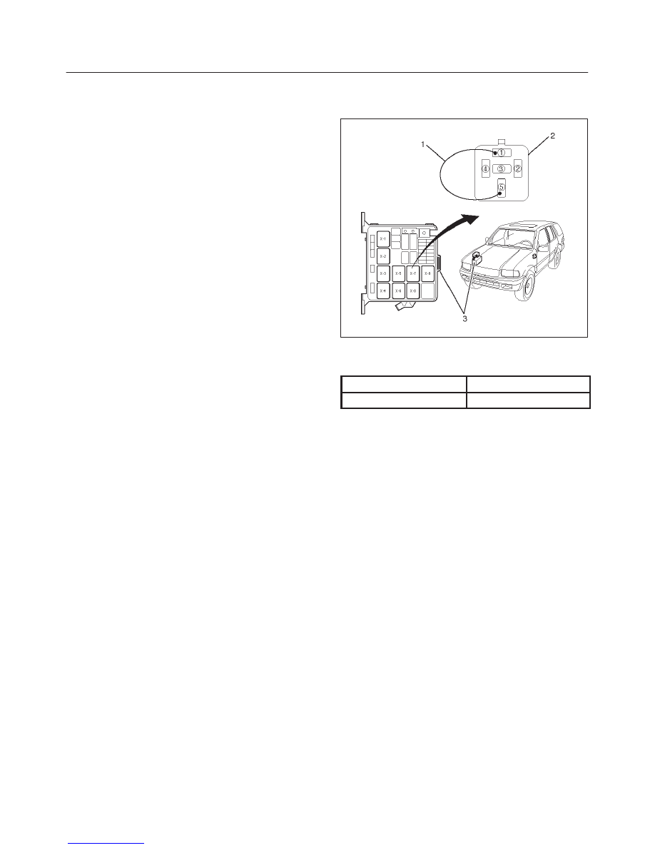
4. Connect the pump relay terminals with a jumper
wire(1) as shown and start the fuel pump to measure
delivery.
140RW015
CAUTION: Never generate sparks when connecting
a jumper wire.
Delivery
Delivery
15 seconds
0.38 liters minimum
If the measure value is out of standard, conduct the
pressure test.
Pressure test
For the pressure test to the fuel system, see Section 6E
“Fuel Control System”.
6C–6
ENGINE FUEL (6VD1 3.2L)
Fuel Pump
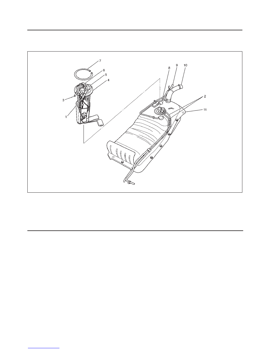
Fuel Pump and Associated Parts
140RX004
Legend
(1) Fuel Feed Port
(2) Fuel Tube/Quick Connector
(3) Fuel Return Port
(4) Fuel Pump and Sender Assembly
(5) Connector; Fuel Feed Pump
(6) Connector; Fuel Level Sensor
(7) Snap Ring
(8) Hose; Evaporative Fuel
(9) Hose; Air Breather
(10) Hose; Fuel Filler
(11) Fuel Tank Assembly
Removal
CAUTION: When repair to the fuel system has been
completed, start engine and check the fuel system
for loose connection or leakage. For the fuel system
diagnosis, see Section “Driveability and Emission”.
1. Disconnect battery ground cable.
2. Loosen fuel filler cap.
3. Support underneath of the fuel tank assembly (11)
with a lifter.
4. Remove fuel tank assembly(11). Refer to “Fuel Tank
Removal” in this section.
5. Remove Fuel Tube/Quick Connector (2).
NOTE: Handling of the fuel tube sure to refer “Fuel
Tube/Quick Connector Fittings” in this section.
6. Remove fuel pump and sender (FPAS) assembly (4)
fixing snap ring and remove the FPAS assembly.
NOTE: After removing pump assembly (4), cover fuel
tank to prevent any dust entering.
Installation
1. Install FPAS assembly(4).
2. Install Fuel Tube/Quick Connector (2).
NOTE: Handling of the fuel tube sure to refer “Fuel
Tube/Quick Connector Fittings” in this section.
3. Install fuel tank assembly(11). Refer to “Fuel Tank
Installation”.
4. Fill the tank with fuel and tighten fuel filler cap.
5. Connect battery ground cable.
6C–7
ENGINE FUEL (6VD1 3.2L)
Fuel Tube / Quick – Connector Fittings
Precautions
f
Lighting of Fires Prohibited.
f
Keep flames away from your work area to prevent the
inflammable from catching fire.
f
Disconnect the battery negative cable to prevent
shorting during work.
f
When welding or conducting other heat-generating
work on other parts, be sure to provide pretreatment
to protect the piping system from thermal damage or
spattering.
Cautions During Work
Do not expose the assembly to battery electrolyte or do
not wipe the assembly with a cloth used to wipe off spilt
battery electorolyte.
The piping wet with battery electrolyte cannot be used.
Be careful not to give a bending or twisting force to the
piping during the work. If deformed, replace with a new
piping.
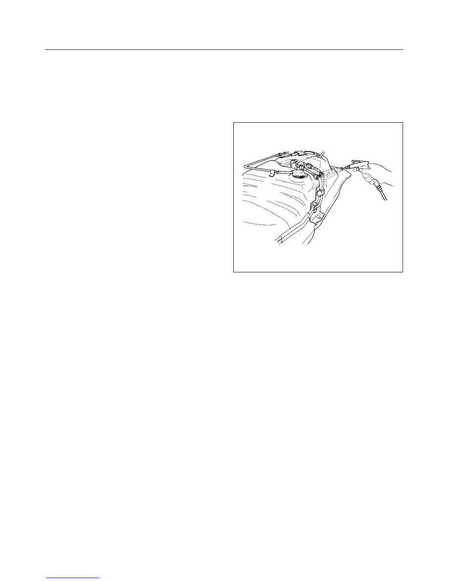
Removal
1. Open the fuel cap to relieve the fuel pressure in the
tank.
If the fuel quick-connect fittings are dusty, clean with
an air blower, etc. and then remove it.
141RW036
As some pressure may remain in the piping, cover the
connector with a cloth, etc. to prevent the splashing
of fuel in the first disconnection of the piping.
6C–8
ENGINE FUEL (6VD1 3.2L)
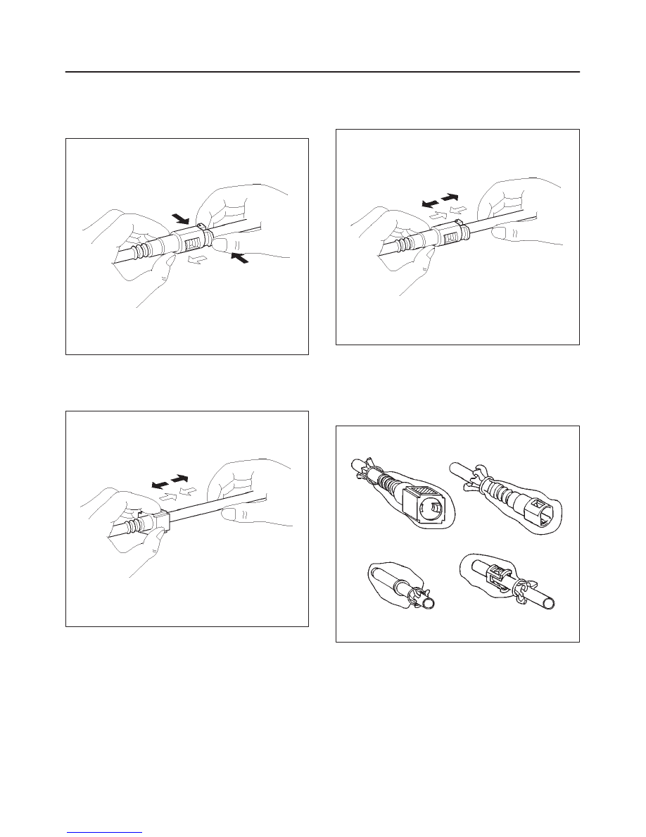
2. For removal of the delivery pipe (feeding fuel to the
engine), hold the connector in one hand, and hold the
retainer tab with the other hand and pull out the
connector, as illustrated. The pipe can be removed
with the retainer attached.
141RW019
3. For removal of the return pipe (returnig fuel to the
tank), hold the pipe in one hand, and pull out the
connentor with the other hand while pressing the
square relieve button of the retainer, as illustrated.
141RW020
NOTE: This work should be done by hands. Do not use
any tools. Should the pipe can hardly be removed from
the connector, use a lubricant (light oil) and/or push and
pull the connector longitudinally until the pipe is removed.
141RW021
When reusing the delivery pipe retainer, reuse
without removing the retainer from the pipe. If the
retainer is damaged or deformed, however, replace
with a new retainer.
Cover the connectors removed with a plastic bag, etc.
to prevent the entry of dust or rain water.
141RW022
Нет комментариевНе стесняйтесь поделиться с нами вашим ценным мнением.
Текст