Isuzu Rodeo UE. Service manual — part 492
TRANSMISSION CONTROL SYSTEM (4L30–E)
7A1–87
f
An intermittent or incorrect engine speed signal may
set a DTC P1870.
Test Description
The numbers below refer to the step numbers on the
diagnostic chart:
2. This test checks the indicated range signal to the
actual selected range. A faulty switch could set a
DTC P1870.
3. This test checks the torque converter for slippage
while in a commanded lockup state.
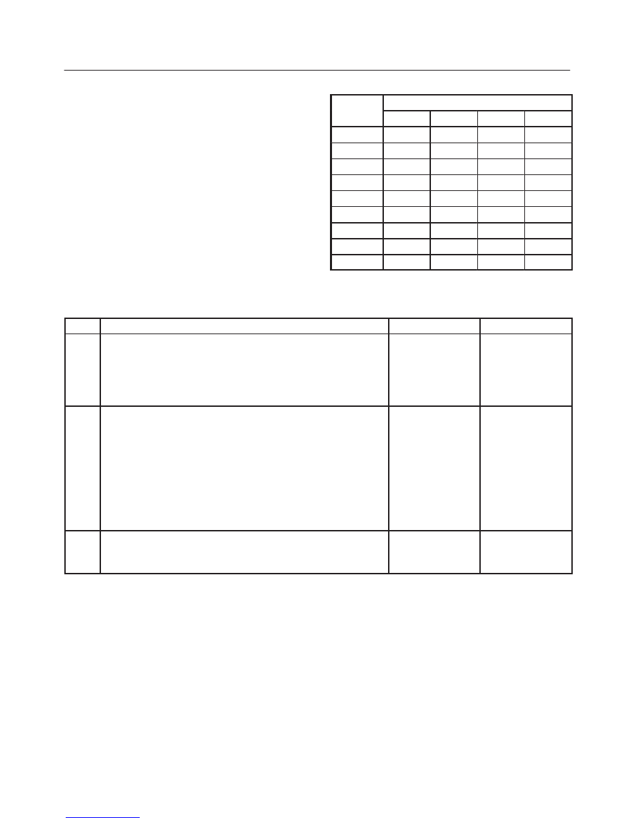
Range Switch Logic Table
Range
Range Switch Pin
g
Position
A
B
C
P(G)
Park
ON
OFF
OFF
ON
Reverse
ON
ON
OFF
OFF
Neutral
OFF
ON
OFF
ON
D4
OFF
ON
ON
OFF
D3
ON
ON
ON
ON
2
ON
OFF
ON
OFF
L
OFF
OFF
ON
ON
Illegal
OFF
OFF
OFF
OFF
Illegal
OFF
OFF
OFF
ON
DTC P1870 Transmission Component Slipping
Step
Action
Yes
No
1
Were you sent here from the “Powertrain On–Board Diagnostic
(OBD) System Check”?
Go to Step 2
Go to OBD
System Check
Refer to
Driveability and
Emission in
Engine section
2
1. Install the scan tool.
2. With the engine “off”, turn the ignition switch “on”.
NOTE: Before clearing DTC(s), use the scan tool to record “Freeze
Frame” and “Failure Records” for reference, as data will be lost
when the “Clear Info” function is used.
3. Record the DTC “Freeze Frame” and “Failure Records”.
4. Apply the brake pedal.
5. Select each transmission range: D1, D2, D3, D4, N, R, and P.
Does each selected transmission range match the scan tool “TR
Switch” display?
Go to Step 3
Go to “Range
Switch Logic
Table”
3
Drive the vehicle in 4th gear while the TCC is engaged.
At any time is the “TCC Slip Speed” greater than 130 rpm for 8
seconds while the TCC is engaged?
Go to System
Diagnosis Charts
Go to Diagnostic
Aids
MANUAL TRANSMISSION
7B–1
RODEO
TRANSMISSION
MANUAL TRANSMISSION MUA 5C (4X2, 4X4) AND
TREMEC T5R(4X2)
CONTENTS
Service Precaution
7B–2
. . . . . . . . . . . . . . . . . . . . . .
General Description
7B–2
. . . . . . . . . . . . . . . . . . . . .
Diagnosis (MUA)
7B–5
. . . . . . . . . . . . . . . . . . . . . . . .
Diagnosis (TREMEC T5R)
7B–6
. . . . . . . . . . . . . . . .
Rear Oil Seal (4X2)
7B–7
. . . . . . . . . . . . . . . . . . . . . .
Disassembled View
7B–7
. . . . . . . . . . . . . . . . . . . .
Removal
7B–7
. . . . . . . . . . . . . . . . . . . . . . . . . . . . .
Installation
7B–7
. . . . . . . . . . . . . . . . . . . . . . . . . . . .
Transmission (MUA)
7B–8
. . . . . . . . . . . . . . . . . . . . .
Disassembled View
7B–8
. . . . . . . . . . . . . . . . . . . .
Removal
7B–9
. . . . . . . . . . . . . . . . . . . . . . . . . . . . .
Installation
7B–13
. . . . . . . . . . . . . . . . . . . . . . . . . . . .
Transmission (TREMEC T5R)
7B–18
. . . . . . . . . . . .
Disassembled View
7B–18
. . . . . . . . . . . . . . . . . . . .
Removal
7B–19
. . . . . . . . . . . . . . . . . . . . . . . . . . . . .
Installation
7B–21
. . . . . . . . . . . . . . . . . . . . . . . . . . . .
Transmission Case
7B–25
. . . . . . . . . . . . . . . . . . . . . .
Major Component (MUA, 4X2)
7B–25
. . . . . . . . . .
Disassembly
7B–26
. . . . . . . . . . . . . . . . . . . . . . . . . .
Reassembly
7B–27
. . . . . . . . . . . . . . . . . . . . . . . . . .
Transmission Case and Transfer Case
7B–30
. . . . .
Major Component (MUA, 4X4)
7B–30
. . . . . . . . . .
Disassembly
7B–31
. . . . . . . . . . . . . . . . . . . . . . . . . .
Reassembly
7B–34
. . . . . . . . . . . . . . . . . . . . . . . . . .
Intermediate Plate with Gear Assembly,
Detent, Shift Arm, and
Interlock Pin (MUA)
7B–40
. . . . . . . . . . . . . . . . . . . . . .
Disassembled View
7B–40
. . . . . . . . . . . . . . . . . . . .
Disassembly
7B–41
. . . . . . . . . . . . . . . . . . . . . . . . . .
Inspection and Repair
7B–42
. . . . . . . . . . . . . . . . . .
Reassembly
7B–43
. . . . . . . . . . . . . . . . . . . . . . . . . .
Reverse Gear and 5th Gear (MUA)
7B–44
. . . . . . . .
Disassembled View
7B–44
. . . . . . . . . . . . . . . . . . . .
Disassembly
7B–45
. . . . . . . . . . . . . . . . . . . . . . . . . .
Inspection and Repair
7B–47
. . . . . . . . . . . . . . . . . .
Reassembly
7B–47
. . . . . . . . . . . . . . . . . . . . . . . . . .
Top Gear Shaft, Main Gear Shaft, and
Counter Gear Shaft (MUA)
7B–53
. . . . . . . . . . . . . . .
Disassmebled View
7B–53
. . . . . . . . . . . . . . . . . . . .
Disassembly
7B–54
. . . . . . . . . . . . . . . . . . . . . . . . . .
Inspection and Repair
7B–55
. . . . . . . . . . . . . . . . . .
Reassembly
7B–58
. . . . . . . . . . . . . . . . . . . . . . . . . .
Transmission Case (TREMEC T5R)
7B–64
. . . . . . .
Disassembled View
7B–64
. . . . . . . . . . . . . . . . . . . .
Disassembly
7B–65
. . . . . . . . . . . . . . . . . . . . . . . . . .
Inspection and Repair
7B–71
. . . . . . . . . . . . . . . . . .
Reassembly
7B–76
. . . . . . . . . . . . . . . . . . . . . . . . . .
Mainshaft (TREMEC T5R)
7B–82
. . . . . . . . . . . . . . . .
Disassembled View
7B–82
. . . . . . . . . . . . . . . . . . . .
Disassembly
7B–82
. . . . . . . . . . . . . . . . . . . . . . . . . .
Reassembly
7B–85
. . . . . . . . . . . . . . . . . . . . . . . . . .
Input Shaft (TREMEC T5R)
7B–87
. . . . . . . . . . . . . . .
Disassembled View
7B–87
. . . . . . . . . . . . . . . . . . . .
Disassembly
7B–87
. . . . . . . . . . . . . . . . . . . . . . . . . .
Reassembly
7B–88
. . . . . . . . . . . . . . . . . . . . . . . . . .
Input Bearing Retainer (TREMEC T5R)
7B–89
. . . .
Disassembled View
7B–89
. . . . . . . . . . . . . . . . . . . .
Disassembly
7B–89
. . . . . . . . . . . . . . . . . . . . . . . . . .
Reassembly
7B–89
. . . . . . . . . . . . . . . . . . . . . . . . . .
Counter Shaft (TREMEC T5R)
7B–90
. . . . . . . . . . . .
Disassembled View
7B–90
. . . . . . . . . . . . . . . . . . . .
Disassembly
7B–90
. . . . . . . . . . . . . . . . . . . . . . . . . .
Reassembly
7B–91
. . . . . . . . . . . . . . . . . . . . . . . . . .
Extension Housing (TREMEC T5R)
7B–92
. . . . . . . .
Disassembled View
7B–92
. . . . . . . . . . . . . . . . . . . .
Disassembly
7B–92
. . . . . . . . . . . . . . . . . . . . . . . . . .
Reassembly
7B–93
. . . . . . . . . . . . . . . . . . . . . . . . . .
Shift Cover (TREMEC T5R)
7B–94
. . . . . . . . . . . . . .
Disassembled View
7B–94
. . . . . . . . . . . . . . . . . . . .
Disassembly
7B–94
. . . . . . . . . . . . . . . . . . . . . . . . . .
Reassembly
7B–95
. . . . . . . . . . . . . . . . . . . . . . . . . .
Pre-Installation Checks (TREMEC T5R)
7B–98
. . . .
Main Data and Specifications
7B–100
. . . . . . . . . . . . .
Special Tools (MUA)
7B–106
. . . . . . . . . . . . . . . . . . . . .
Special Tools (TREMEC T5R)
7B–108
. . . . . . . . . . . . .
7B–2
MANUAL TRANSMISSION
Service Precaution
WARNING: THIS VEHICLE HAS A SUPPLEMENTAL
RESTRAINT SYSTEM (SRS). REFER TO THE SRS
COMPONENT AND WIRING LOCATION VIEW IN
ORDER TO DETERMINE WHETHER YOU ARE
PERFORMING SERVICE ON OR NEAR THE SRS
COMPONENTS OR THE SRS WIRING. WHEN YOU
ARE PERFORMING SERVICE ON OR NEAR THE SRS
COMPONENTS OR THE SRS WIRING, REFER TO
THE SRS SERVICE INFORMATION. FAILURE TO
FOLLOW WARNINGS COULD RESULT IN POSSIBLE
AIR BAG DEPLOYMENT, PERSONAL INJURY, OR
OTHERWISE UNNEEDED SRS SYSTEM REPAIRS.
CAUTION: Always use the correct fastener in the
proper location. When you replace a fastener, use
ONLY the exact part number for that application.
ISUZU will call out those fasteners that require a
replacement after removal. ISUZU will also call out
the fasteners that require thread lockers or thread
sealant. UNLESS OTHERWISE SPECIFIED, do not
use supplemental coatings (Paints, greases, or other
corrosion inhibitors) on threaded fasteners or
fastener joint interfaces. Generally, such coatings
adversely affect the fastener torque and the joint
clamping force, and may damage the fastener. When
you install fasteners, use the correct tightening
sequence and specifications. Following these
instructions can help you avoid damage to parts and
systems.
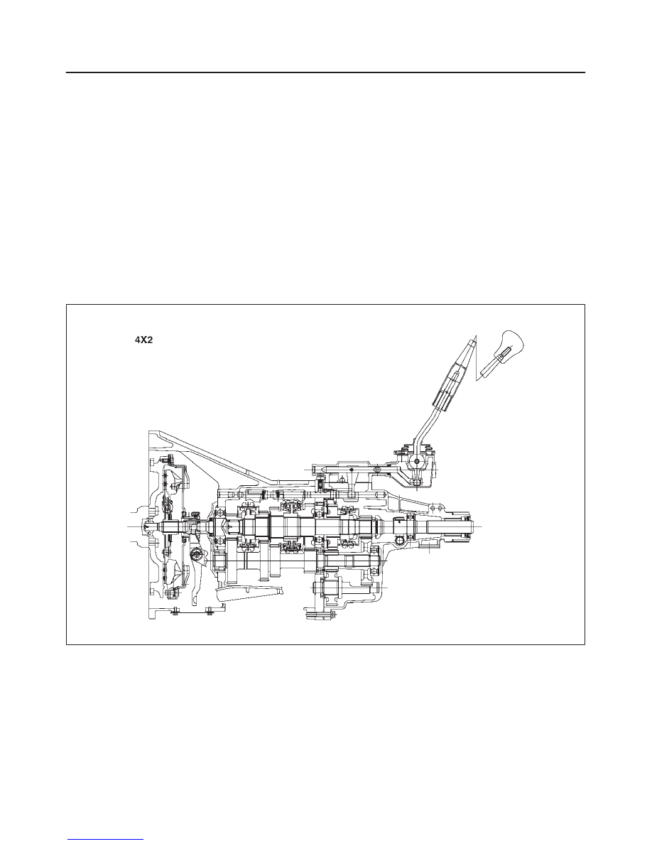
General Description
MUA5C Transmission
A07RW039
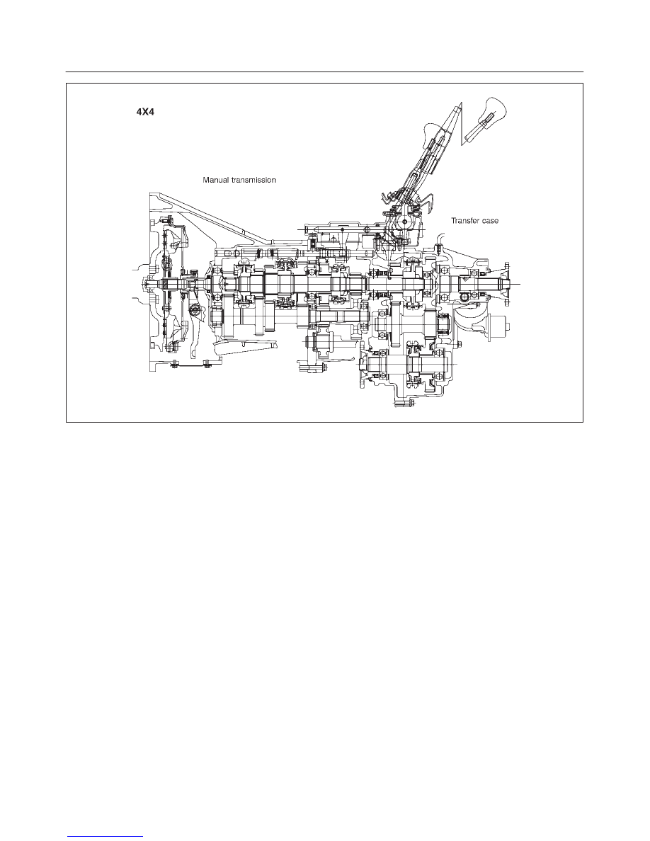
MANUAL TRANSMISSION
7B–3
A07RW040
The MUA5C is a constant mesh transmission,
synchronized in all speeds. The transmission is designed
for a great reduction of the shift effort and the quietest
possible operation.
Principle parts of the transmission are the integral clutch
housing, intermediate plate, the transfer case, the rear
cover, and the gears.
The transmission control box and transfer control box are
built into the transmission and transfer case.
Нет комментариевНе стесняйтесь поделиться с нами вашим ценным мнением.
Текст